
Floor Heating Thermostat Wiring: Connections, Sensor & Spacing
A practical guide to wiring an electric film floor to a programmable or wifi thermostat — connection points, sensor and spacing.
An electric film floor only earns its keep if the floor heating thermostat is wired correctly. This walkthrough covers the part people usually get wrong on site — the connections between the thermostat, the heating film’s supply, and the floor sensor — using a standard wiring diagram as the reference. It assumes you are comfortable with a multi-meter and the basics of isolation, and it is written for a film system specifically, because film’s low thermal mass makes the control wiring more influential than it is on a thick screed floor.
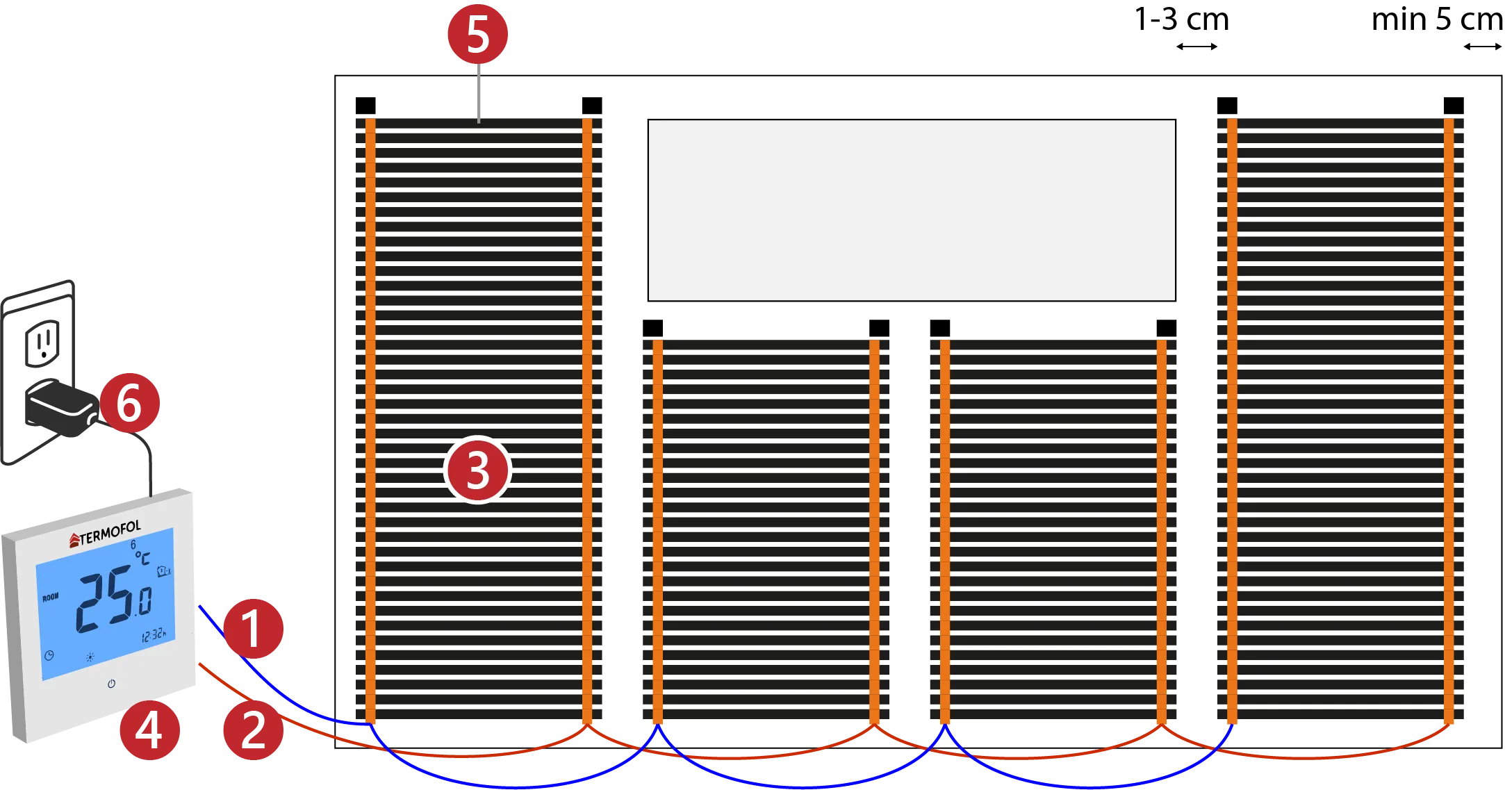
Reading the diagram before you touch a wire
On a film system the thermostat is a switching point, not a heat source: it reads a sensor, decides whether the floor needs heat, and switches the film circuit on or off. The numbered nodes on the diagram trace that path — from the incoming supply, through the thermostat, out to the film’s copper busbars, with the floor sensor wired back to the thermostat’s sensing terminal. Keep the polarity of the sensor terminals right, or the room simply will not read correctly.
A habit worth forming early: photograph the finished wiring before the box is closed. When a fault surfaces months later, a clear photo of which wire went where is worth more than any recollection, and it costs nothing at install time.
The connection points, one by one
Incoming live and neutral
Terminate the circuit supply at the thermostat’s mains terminals. This is the point that gets switched.
Load side to the film
Run the load terminals out to the film supply wires — these join at the busbar junction you prepared during layout.
Floor sensor
Lay the floor sensor in a channel between two film sheets, centred in the room, not under a piece of furniture. Wire it to the sensor terminals.
Earth bonding
Bond the film’s earth screen and any exposed metal to the circuit earth, exactly as the manual shows.
Commission
Power up, set the programme and check the thermostat reads the floor sensor temperature before closing the box.
Spacing rules that make the heat even
Two measurements on the diagram do most of the work: film sheets sit 1–3 cm apart, and the heating area stays at least 5 cm clear of walls and fixed items. That gap is not cosmetic — it stops hot spots where sheets sit too close and stops heat being blocked against a wall. If you crowd the sheets or run them right to a skirting, you get a floor that is warm in patches and overworked in others.
Sensor placement in practice
- Centre the floor sensor in the room, away from doorways and draughts.
- Keep it between two heating sheets, not beneath one — it should sense the floor, not the element.
- Leave a serviceable run so the sensor wire reaches the thermostat without kinks.
- If the thermostat supports an air sensor too, enable both so a warm day does not leave the floor running.
Wiring scenarios you will meet
The single-room diagram is the cleanest case, but most jobs are not that simple, so it is worth knowing how the same thermostat principle stretches across the situations installers actually see:
One room, one thermostat
The classic case: a single film zone, a single load circuit, one floor sensor. This is the diagram above, and it is the base case everything else builds on.
Two or more zones, several thermostats
Each room gets its own thermostat and its own load run back to the film. The thermostats share the incoming supply but switch independently, so schedules stay per-room.
One thermostat driving more film than it can switch
If the film’s connected load exceeds the thermostat’s contact rating, split the load with a relay or contactor driven by the thermostat, rather than overloading its contacts. This is the failure most often misdiagnosed as a bad thermostat.
Multiple rooms on one open zone
Where two rooms are truly one open heated area with a single schedule, one thermostat and one sensor can serve both — provided the sensor sits in a representative spot and the load is within rating.
If your layout does not obviously fit one of these, that is the point where a quick wiring sketch before you start saves the most time. The thermostat range pages show each model’s contact rating and sensor wiring so you can match the controller to the film load before the box is on the wall.
Smart control changes the picture
A basic programmable thermostat holds one schedule; a smart wifi thermostat brings per-day programmes, away mode and app control to the same wiring. The connections stay the same — you are still switching the film circuit — but the thermostat adds logic on top. For an apartment or a single room this is usually the better buy, and it is why our thermostat range leads with wifi models.
What a smart thermostat adds, feature by feature
Once the wiring is right, the difference between a basic and a smart unit is the logic on top, and on a film floor the logic is where the running cost is saved:
- Per-day scheduling — different programmes for weekdays and weekends, so an empty weekday afternoon is not heated.
- Away and frost mode — one button or app action drops the floor to a protective low set-point instead of heating an empty room.
- App control — adjust the schedule or switch the floor on before you arrive, from wherever you are, on the same wiring as a basic unit.
- Floor-plus-air sensing — the thermostat uses the floor sensor for the set-point while an air sensor caps the room, avoiding both overshoot and overheat on a warm day.
- Load handling — a model rated for the film’s connected load switches cleanly, and with a relay it can drive a large zone without stressing its contacts.
None of these change the connections from the diagram earlier in this guide — they are all behaviour on top of the same two-terminal switching circuit. That is the neat part about upgrading control on a film floor: it is a box swap, not a rewire. For the models that match a given film wattage, the smart wifi thermostat and thermostat controls pages list the ratings so the upgrade is planned, not guessed.
What the sensor actually does
The floor sensor is easy to treat as an afterthought, but it is half of what makes the thermostat behave. It is a temperature probe wired back to a sensing terminal on the thermostat; the thermostat compares its reading with the set-point and decides whether to energise the film. Get the placement wrong and the whole system misbehaves even though the wiring is perfect. The working rules:
- Lay the sensor in a channel cut between two film sheets, centred in the heated area — it should read the floor, not the element directly under it.
- Keep it away from doorways, draughts and heavy furniture that would shade it or trap heat.
- Leave a clean run of sensor wire back to the thermostat with no sharp kinks, and do not coil spare wire near the film — the coil reads as a warm spot.
- If the model also has an air sensor, decide which one drives the room. A common and comfortable arrangement is the floor sensor for the set-point with the air sensor as a limiter, so a hot day does not leave the floor running.
On film floors this matters more than on thick screed systems because film responds fast and has little thermal mass to smooth out errors. A sensor in the wrong place produces a floor that cycles, or one that feels cold on one side of the room — both are placement problems, not product problems.
Commissioning and troubleshooting checklist
| Check | How to do it | What it rules out |
|---|---|---|
| Continuity per zone | Measure resistance across each film busbar before the finish goes down | A nicked sheet, a dry joint |
| Sensor resistance | Compare the sensor’s resistance to the thermostat’s table | A damaged or mis-wired sensor |
| Load within rating | Add the zone wattage against the thermostat’s contact rating | Overloaded contacts, early failure |
| Sensor position | Confirm it sits between sheets, not under one | Short-cycling, cold patches |
| RCD test | Press the test button on the residual current device | A circuit that would not trip in a fault |
Run these five before the finish goes on and commissioning becomes a formality rather than a discovery. The one people skip most is the sensor-resistance check, and it is also the one that explains most “my floor reads cold” calls — the wire is fine, but the sensor was nicked during layout and the thermostat is reading nonsense. A graphene heating film layout and its control are only as good as the connections at the box, and this checklist is how the good ones stay good.
A safety note before the power goes on
Because a film floor is an electrical heating circuit embedded under a floor finish, the box is where safety is decided, not just the film itself. Always isolate the circuit at the consumer unit before any work, confirm the film’s earth screen is bonded to the circuit earth exactly as the manual shows, and never exceed the thermostat’s contact rating. Where the circuit supplies a wet room or an outdoor area, a residual current device with a suitable rating is not optional. These rules are not about any one brand — they are what keeps an embedded heating element safe for the years it sits under the floor. A qualified electrician should carry out the work to the local code, and the notes at the foot of every case page repeat that for a reason.
Questions installers ask
Can I run two rooms from one thermostat?
What if my film sheets add up to more than the thermostat rating?
Which sensor terminals are which?
Why does my floor read cold after power-up?
Do I really need a floor sensor for film?
Can the wifi thermostat work without a router at install?
Which thermostat matches my film wattage?
Tell us the room count and film wattage and we will pair a compatible programmable or wifi thermostat.
This guide is for qualified electricians. Follow the specific wiring diagram supplied with your thermostat and the film’s manual, and always comply with local electrical codes.