
A 24-hour station cannot close for a conventional retrofit
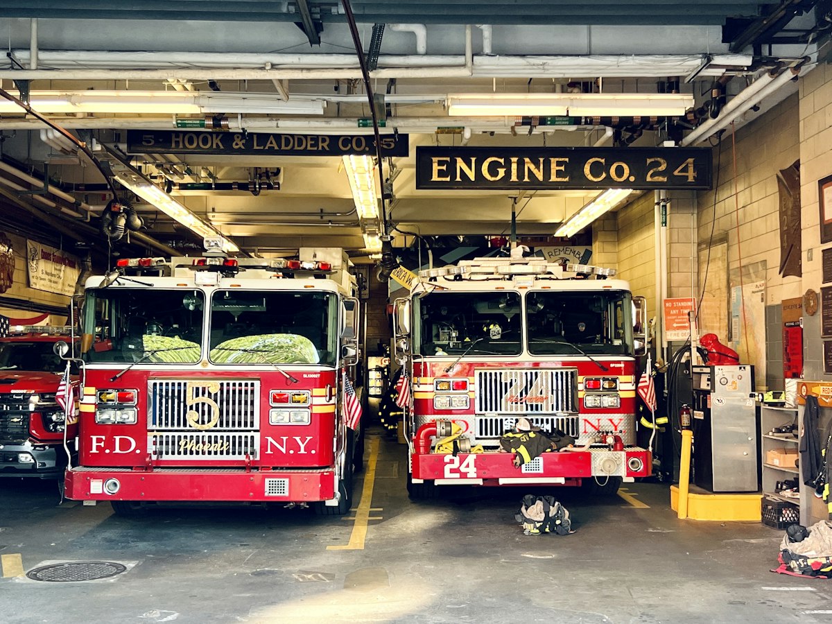
Fire stations are a difficult building to keep warm and an even more difficult one to renovate. The apparatus bay is a concrete floor sitting at the edge of an open door, wet from hoses and tyres, crossed by boots carrying equipment at all hours. The living quarters behind it run around the clock, with shifts sleeping while the next crew works. When a municipal authority asked us to plan floor heating for a 1990s station, the binding constraint was never the heating technology. It was that the building could not stop operating: apparatus had to leave the bay on every call, and no work could block a route or close a door for more than a few hours. This article documents how that retrofit was specified, phased and delivered, and what another municipality should expect when planning the same project.
As with all case material here, the numbers come from project records and factory data rather than a marketing model. Where a figure is an estimate or a design assumption, it is described as one, and the energy results from the first season are reported alongside the conditions they were measured under. The point of the story is not that every station needs the same system, but that the phasing and the zoning matter as much as the hardware.
Michael Thompson, Municipal Projects Lead, SunAura Thermal
Why the station had a cold-floor problem in the first place
The building followed a pattern common to stations of its era: a large apparatus bay with high-bay doors and a concrete slab, attached to two-storey quarters heated with warm air. Three complaints had been recurring for years, and each pointed back to the floor rather than the air temperature.
The bay slab. A high-bay door opens dozens of times a day, and every opening dumps cold air onto a slab that stores it. Warm air rises to the high ceiling, so the thermostat at head height could read 16 °C while the floor sat at 8–10 °C. Crews pulling gear on and off apparatus were working at floor level, where the cold actually was. The slab also stayed wet longer than it should: hoses, tyres and boots brought water in, and a cold floor dries slowly, keeping the bay damp through the winter.
The gear and equipment. Turnout gear stored near the bay needs to dry between calls; damp gear is heavier, less comfortable and slower to put on. A warm, dry floor changes the environment of the whole ground level, not just the spot a heater points at.
The quarters. The dormitory and day rooms were comfortable enough at the thermostat but had cold floors in the morning and uneven heat between rooms. The authority also wanted a system that could be zoned, so an unoccupied dorm room was not heated to the same level as the watch room.

Why a thin electric mat was chosen over the alternatives
Three options were assessed at the feasibility stage, and the building’s operating constraints eliminated two of them quickly.
A hydronic system would have meant a new screed across the bay, a boiler or heat-pump connection, and manifold work in a building with no spare plant room. More importantly, the wet trades and drying time would have taken zones of the floor out of use for days at a time, which the station could not grant. Forced-air heaters, the existing approach, were cheap to add but had already demonstrated the core failure: they heat the ceiling of a high-bay space while the slab stays cold, and they move dust and exhaust around the very apparatus being cleaned.
An electric heating mat solved the problems in the right order. At roughly 3–4 mm thick, it could be embedded in a thin new topping rather than a full screed, so floor levels rose only slightly and thresholds could be adjusted with small details. It zones naturally — each bay and each room is its own circuit — and it has no moving parts, no fluids and no plant room. The heat is delivered at the floor, where the problem was, and the same warm slab dries the wet patches that a cold one keeps alive. The running cost question was examined honestly rather than assumed away, and the first-season figures are reported below.
| Option | Build-up and disruption | Fit with 24/7 operation | Zoning |
|---|---|---|---|
| Hydronic screed | 50 mm+; wet trades, drying days | Poor: bays out of use for stretches | Good, but needs plant room |
| More warm-air units | Minimal floor work | Good, but heats the ceiling | Coarse; cold slab remains |
| Thin electric mat | Thin topping; work in strips | Strong: one bay at a time | Per bay and per room |
Zoning the building around how a station actually runs
The electrical design was drawn from the station’s daily routine rather than from its room labels. The final layout split the floor into zones that match the way the building is occupied.
The apparatus bay was divided into three zones, one per apparatus position, plus a strip along the workbench and gear storage. Each bay can heat independently, so a position temporarily empty for maintenance is not heated, and the bench zone — where crews actually stand to prepare equipment — gets priority. The bay runs on a floor probe rather than an air sensor, because the whole point of the system is the slab temperature, and the control holds the floor at a steady setpoint rather than chasing the air temperature every time the big door opens.
The quarters were zoned by function: the watch room and corridor as one always-occupied zone, the dorm rooms as separate setback zones, and the day room and kitchen grouped together. A smart thermostat per zone allows scheduling around the shift pattern, with night setback in the day rooms and morning warm-up timed to the change of watch. Because the building is occupied at every hour, no zone is ever fully switched off; the setback simply holds a lower floor temperature.
Phasing the work so every call could still be answered
This was the part of the project that required more planning than the engineering, and it is the detail most likely to be underestimated on a similar job. The work was broken into packages that never left the station without a usable route for every piece of apparatus.
Bay work, one position at a time. The existing slab was prepared in sections matching the apparatus zones. The mat was laid and covered with a thin, fast-curing topping, and the section was kept clear only for the topping’s cure — scheduled around the duty roster so the apparatus from that position could temporarily share another bay. At no point did fewer than two apparatus positions remain fully available, which was the authority’s hard rule.
Quarters work around the shift rota. Rooms were done between shift changes, with the crew moved to a spare dorm where needed. The thin build-up meant doors and built-in furniture needed no changes, and the electrical work — new circuits back to the panel — was run in existing service routes to avoid chasing walls in occupied rooms.
Commissioning before the final finish. Each mat was tested for continuity and insulation resistance before the topping went down, and again through the thermostat afterward. The per-zone certificates were handed into the municipal project file, because public procurement keeps the documentation long after the contractors leave. A final handover session walked the station’s maintenance team through the controls and the setback schedule, so the system is run deliberately rather than left at whatever the installers set.
Load planning, circuits and the electrical panel
A retrofit lives or dies on the existing electrical supply, and the panel assessment was one of the first actions rather than the last. The bay zones and the quarter zones were each treated as dedicated circuits, with the total load calculated from the actual heated area rather than the room footprint.
The arithmetic is straightforward and worth showing. A bay zone of 35 m² at 150 W/m² draws 5.25 kW, which at 240 V is about 22 A — a dedicated circuit with a contactor, because the thermostat’s own relay is not the switching device for a load that size. Each zone was sized the same way, and the panel was checked for spare capacity before any mat was ordered; the small amount of additional distribution work was included in the original budget rather than discovered on site. RCD protection was specified across the floor circuits, the standard arrangement for embedded heating in a wet environment.
One coordination point is specific to municipal buildings: the electrical work often has to be delivered by an approved contractor under a framework agreement, separate from the heating supplier. The technical specification therefore had to state the load, the circuit count and the contactor rating clearly enough for the framework contractor to quote against, without needing the heating design to be redone. Writing the spec to that level of detail is slower than a private order, but it is what keeps a public tender from drifting.
First-season results and the honest running-cost picture
The system was commissioned before the heating season and monitored through the first winter, with the figures reported against the weather that actually occurred rather than an average year. Three observations are worth recording.
The bay floor held its setpoint across door openings in a way the old air heating never approached: the slab no longer drops to single-digit temperatures, and wet patches dry within a fraction of the previous time. The crews’ own feedback — the practical measure in a building like this — changed from complaints about cold feet and damp gear to no comments at all, which is usually what success sounds like in an occupied building.
Energy use needs the careful framing it always deserves. The bay zones, which hold a steady floor temperature through a high-bay space, account for the majority of consumption, and the total is a real operating cost the authority now budgets for. Two design choices keep it contained: the floor-probe control, which does not over-react every time a door opens, and the per-bay zoning, which means empty positions are not heated. The quarter zones use the setback schedule around shifts. A fair comparison with the old warm-air system has to credit the new system for the drying and comfort it actually delivers, not just compare kilowatt-hours between two systems that produced different conditions.
Data and evidence
The project figures — zone areas such as a 35 m² bay at 150 W/m² drawing roughly 5.25 kW, the thin mat build-up, and the test sequence of continuity and insulation resistance before and after the floor finish — are taken from the project’s specification and handover records. The first-season observations are reported as monitored outcomes, with the caveat that a single winter’s energy figures reflect that year’s weather and should not be annualised into a guarantee.
The product and factory details follow SunAura factory records: heating mats manufactured in Qingdao, Huangdao District since 2008, ISO 9001, ISO 14001 and ISO 45001 management systems, CE and RoHS marked products, LVD and EMC tested, exported to more than 50 countries. Every mat supplied for the project carried the factory continuity and insulation checks, and the per-zone electrical certificates were included in the municipal handover documentation.
Consistent with our usual practice, certificate numbers are not published in articles because audit cycles change the underlying documents; the current Declaration of Conformity and the test reports are provided as part of the tender response and can be checked against the equipment actually installed.
FAQ
Can a working fire station stay operational during this kind of retrofit? Yes, if the work is phased one apparatus position at a time with a hard rule that at least two positions remain available. The schedule has to be built around the duty roster and the cure time of the topping, not the other way round.
Why electric rather than water-based heating? The thin mat fits a small new build-up, needs no wet screed or plant room, zones per bay, and can be installed in sections that match the station’s constraints. Hydronic systems are viable in new builds but are much harder to phase in an occupied building.
Does heating the apparatus bay use a lot of energy? The bay is the largest consumer because it holds a steady slab temperature against frequent door openings. Floor-probe control and per-bay zoning keep the figure in check, and the cost should be judged against the drying and gear-protection benefits the floor provides.
Who holds the test and safety documentation? Every zone is tested before and after the finish, and the certificates go into the municipal project file. Public procurement requires this paper trail, so the specification should name the required tests from the start.
What is the first thing to check on a similar project? The electrical panel. The total load and the number of dedicated circuits have to be established before the heating is specified, and framework electrical contractors need the figures written into the tender documents.
Next step
If you are planning a station or another always-occupied municipal building, send us the floor plan, the bay and room dimensions, the panel capacity and the operating constraints. We will return the zoning layout, the phasing plan, the load and circuit schedule, the test documentation and a quotation, usually within a few working days. The phasing is the part worth getting right first — everything else in a project like this can be engineered on paper, but a missed call cannot.
Michael Thompson, Municipal Projects Lead, SunAura Thermal