
Ethan Sun, Founder & CEO, SunAura Thermal
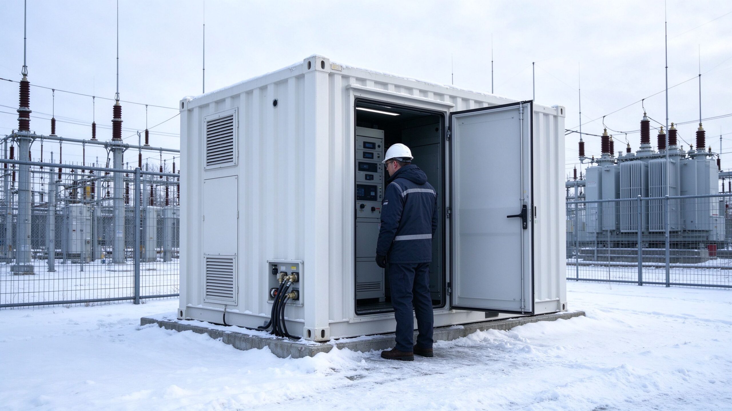
A lithium battery container that sits at -20 °C does not simply run slower. It stops accepting charge. Most LFP battery management systems block charging below roughly 0 °C and only allow full current above about 5 °C, which means a storage site in a cold climate can be physically full of energy capacity and still be unable to absorb power from the grid on a winter night. Heating a container is therefore not a comfort feature. It is the difference between an asset that earns and one that idles.
This case covers a 2 MWh containerised system in a northern climate that had to hold its cells above 5 °C through a winter that touched -25 °C, and why the integrator moved from an air-side heater to a hybrid of wall-mounted radiant film and rack-level contact heating. It is written for buyers and integrators comparing heating options, because the three common approaches differ in cost, uniformity and failure consequence far more than their datasheets suggest.
Why air heating alone struggles in a battery container
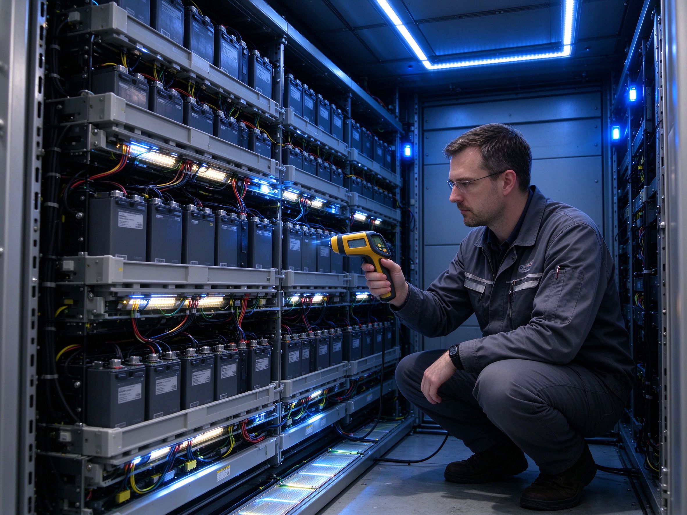
The standard approach on most containers is a PTC air heater with a fan, controlled by the HVAC or the fire panel. It is cheap, it is familiar to every integrator, and it heats the air quickly. The problem is that air carries very little heat per unit volume and the cells have real thermal mass. Warming the air to 15 °C does not mean the cell cores are above 5 °C, particularly in a rack where cells are clamped together and the middle of a module is insulated by its own neighbours.
There is a second issue: air heaters create a strong vertical temperature gradient. Warm air rises to the top of the container, the floor stays cold, and the BMS reports a spread that can exceed 10 K between the top and bottom modules. A BMS that sees a cold module will derate or block charging even when the average container temperature looks acceptable.
The third issue is failure consequence. An air heater that fails in January is discovered when the BMS blocks charging, which is exactly when the site is needed. A distributed heating layer that loses one circuit loses a fraction of the heat and the rest keeps working.
The three heating architectures, compared on the numbers that matter
| Architecture | Typical installed power for a 20 ft / 2 MWh container | Temperature uniformity across racks | Heat-up time from cold soak | Typical installed cost | Main risk |
|---|---|---|---|---|---|
| PTC air heater with fan | 1.5–2.5 kW | Poor; 6–12 K top-to-bottom spread | 3–5 hours for air, longer for cell cores | Lowest per kW | Single point of failure; fans and heaters wear |
| Rack-level contact heating film or pad | 0.8–1.6 kW distributed | Good; 2–4 K spread if zones are balanced | 4–7 hours, but cores warm directly | Medium; scales with rack count | Installation discipline; film must not be over-compressed |
| Wall-mounted radiant film plus air circulation | 1.2–1.8 kW | Moderate to good with low-speed fans | 2–4 hours | Medium | Radiant asymmetry if zones are poorly placed |
| Liquid cooling with heater module | 2–4 kW through coolant | Best; coolant loop equalises | 1–3 hours | Highest | Coolant freeze protection and pump dependency |
The table makes the trade-off visible. Air heating is the cheapest way to add kilowatts and the worst way to add uniformity. Rack-level contact heating adds fewer kilowatts but puts them where the thermal mass actually is. Liquid systems win on uniformity and cost the most, and they inherit a dependency on pumps and coolant that a purely electric heating layer does not have.
How the heating load was actually sized
The container was a standard 20 ft unit with roughly 90 m² of envelope area, insulated with 75 mm polyurethane panels giving a U-value around 0.35 W/m²K including frame thermal bridges.
The design condition was -25 °C outside and a target internal air temperature of 10 °C, which gives a temperature difference of 35 K. Transmission loss is U × A × ΔT, which is 0.35 × 90 × 35, or about 1,100 W. That is the steady-state figure with no solar gain and no internal heat from the battery system itself.
Two corrections were applied. First, the battery system generates some heat during cycling, so the heating load at full charge or discharge is lower, but the design case is an idle cold night with no cycling, which is when the heater carries the whole load. Second, a 35 % margin was added for door openings during maintenance, aged insulation and the cold-soak recovery after a long outage. That gave an installed heating capacity of about 1,500 W.
The final layout was 1,450 W in total: four rack-level film zones at 300 W each, 1,200 W distributed across the module frames, plus one 250 W wall-mounted radiant panel near the door where cold air enters during inspection. The PTC air heater was retained at 600 W but re-purposed as a circulation and backup device rather than the primary heat source.
Where the film goes, and the three rules that decide whether it works
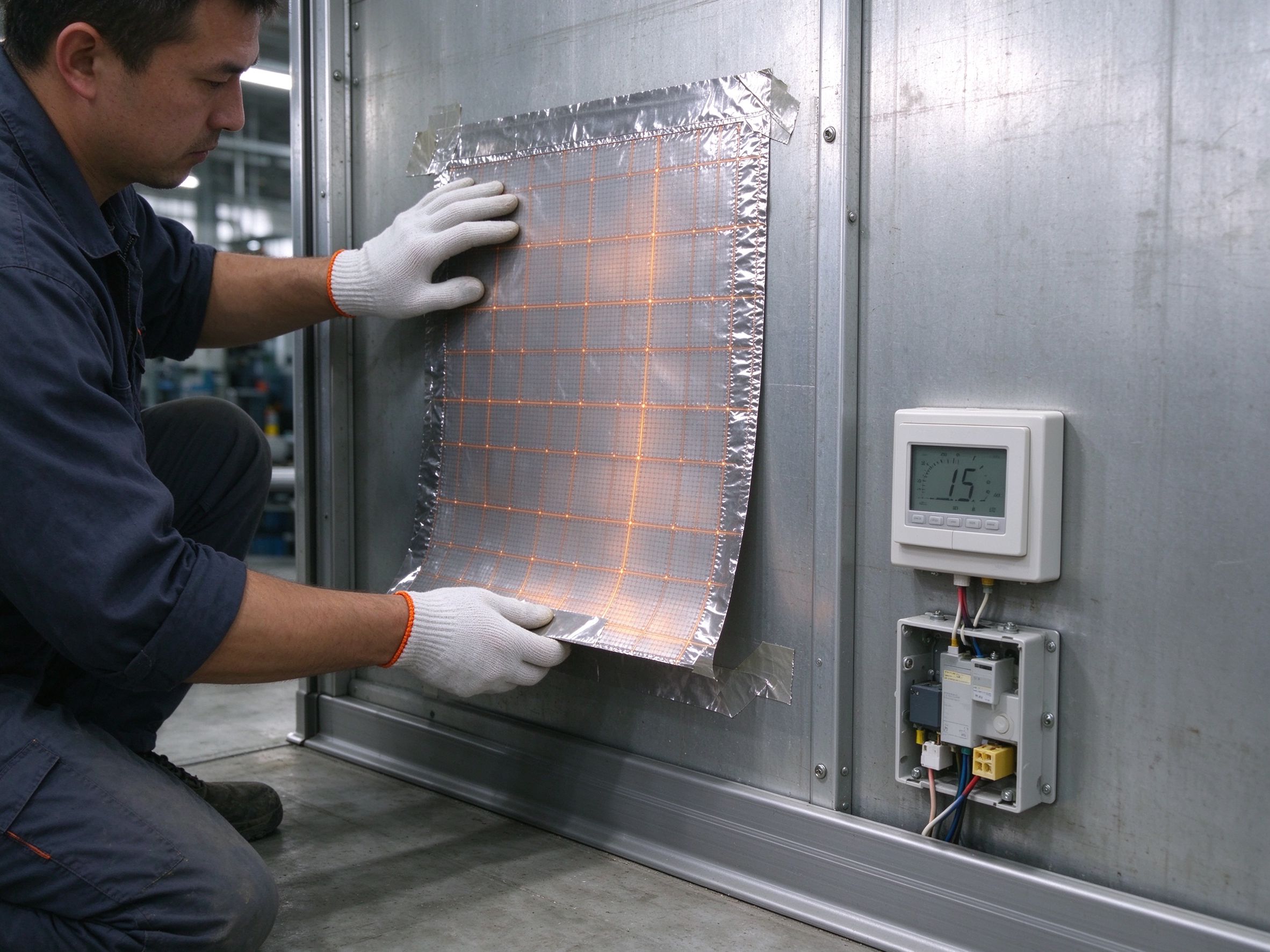
Contact heating film on a battery rack is not the same application as floor heating. Three rules governed the installation.
Rule one: never compress the film against a cell face.
The film was mounted on the module support frame and the back plate, not on the cell faces themselves. Cell cans expand and contract slightly with state of charge and temperature, and a film clamped between a cell and a fixed plate will be abraded at the edges within a few hundred cycles. The gap between film and cell surface was kept at 2–4 mm, with the film radiating to the frame that carries the modules.
Rule two: limit surface temperature, not air temperature.
The film surface was limited to 55 °C by thermostat and by the film’s own power density choice, well below the cell’s acceptable ambient range. A film that runs at 90 °C in a confined rack creates a local hot spot that the BMS will read as a cell temperature anomaly, and the site will trip on a protection that has nothing to do with the battery.
Rule three: zone the racks, not the container.
Four independent film circuits, one per rack, each with its own thermostat and floor-style probe mounted on the rack frame. If one rack is empty during a maintenance swap, its circuit can be isolated without affecting the other three. This is the same logic we apply to underfloor heating zones, and it is the reason a single failed circuit does not take the site down.
Control strategy and measured performance
The control scheme was deliberately simple: heat on when rack frame temperature falls below 5 °C, heat off at 15 °C, with a 3 K differential to prevent short cycling. The wall panel near the door runs on its own thermostat set to 10 °C, because the door area loses heat faster than the racks.
Over the coldest week of the commissioning winter, with outside temperatures between -22 °C and -14 °C, the measured results were:
- Container internal air temperature held between 8.6 °C and 11.2 °C.
- Rack frame surface temperature between 9.4 °C and 13.8 °C, a spread of 4.4 K across the four racks.
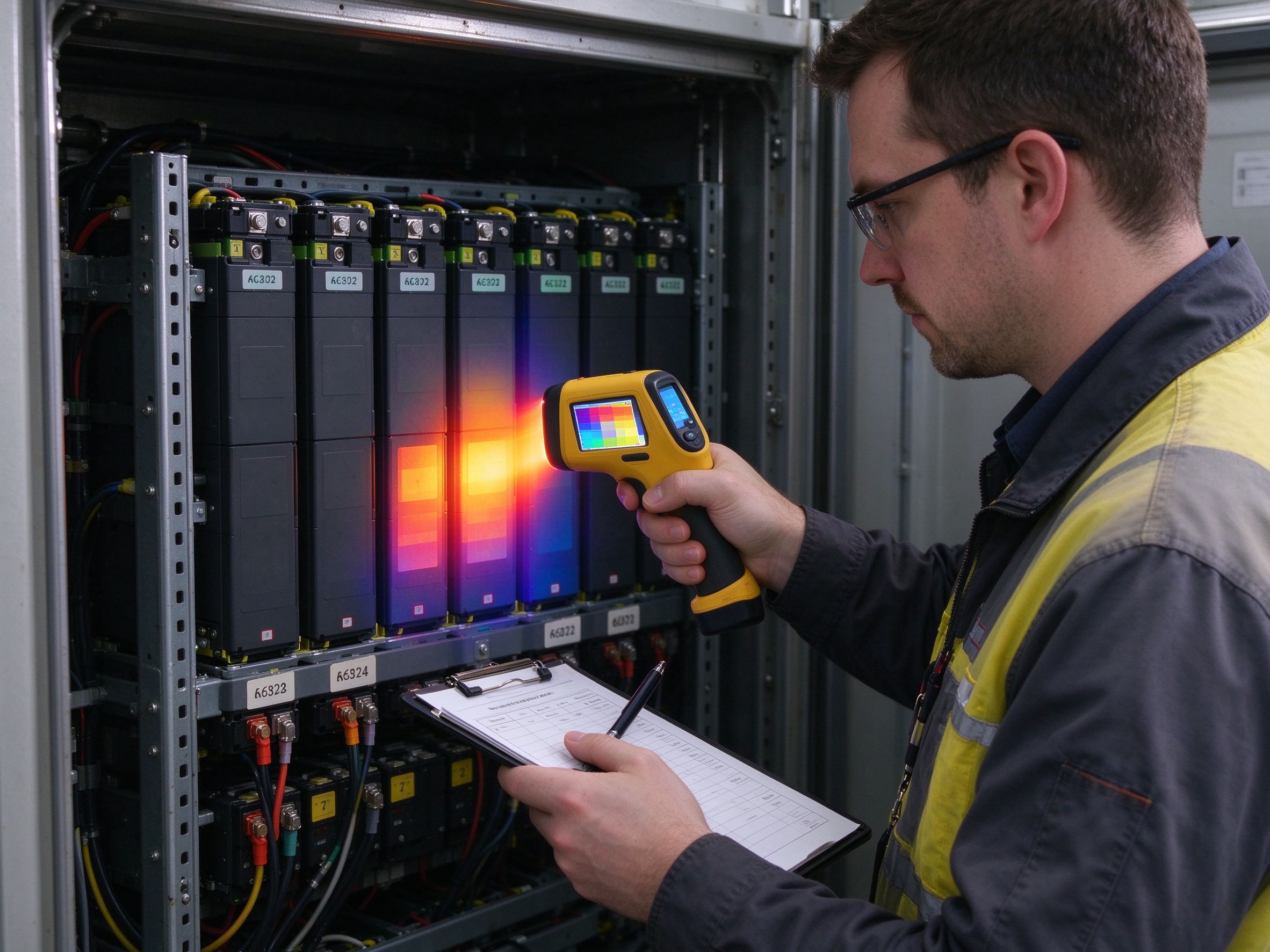
- Cell-top temperature reported by the BMS between 7.1 °C and 10.9 °C, with no charging block events.
- Average heating power over the week was 0.62 kW, with peaks of 1.31 kW during the two coldest nights and after a maintenance door opening.
- Weekly heating energy was 104 kWh, which on the site’s tariff was a small fraction of the value of the charging hours it preserved.
For comparison, the previous winter with the air heater alone had produced repeated charging blocks below -15 °C outside, and a top-to-bottom rack spread that peaked at 11 K. The heating energy was not much lower; the difference was where the heat went.
Selection framework: which architecture for which climate and duty
Mild climates, rarely below -5 °C, cycling daily. A single PTC air heater with a thermostat is adequate and cheapest. The cells generate enough heat during cycling that the heater is mostly a standby device. Do not over-engineer this case.
Cold climates, -10 °C to -25 °C, with idle periods. Air heating alone will block charging. The workable minimum is wall-mounted radiant film plus a low-speed circulation fan, or rack-level contact film if the racks allow access. This is the band where most northern European and northern Chinese sites sit, and it is where the hybrid pays for itself in the first winter.
Severe cold below -25 °C, or sites with long idle periods.
Use both: rack-level contact heating as the primary layer, air circulation for uniformity, and a redundant heater on a separate circuit. Insulation thickness matters more than heater power at this point; upgrading from 75 mm to 100 mm panel reduces transmission loss by roughly a quarter, which is cheaper than adding kilowatts.
Liquid-cooled systems in any cold climate. Specify a coolant heater module in the thermal management unit and treat the electric film as backup for the racks, not as the primary source. The coolant loop gives the best uniformity available, and duplicating it with electric heating is only justified where the pump or the coolant itself is at risk.
Procurement checklist for a container heating package
- Design outside temperature and the number of consecutive days at that temperature.
- Target internal air temperature and the minimum cell temperature the BMS will accept for charging.
- Envelope area, insulation thickness and U-value, including frame thermal bridges.
- Whether the site cycles daily or sits idle for weeks, because idle changes the design case entirely.
- Rack geometry and access: is there a mounting surface behind or beside the modules, and can it be reached for service?
- Required film power density and maximum permitted surface temperature near cells.
- Number of independent zones and whether each needs its own thermostat and probe.
- Electrical supply available inside the container and the rating of the existing distribution.
- Fire and material requirements: flame-retardant rating, low-smoke jacket if specified, and earthing arrangement.
- Monitoring interface: dry contacts, Modbus, or integration into the site SCADA.
- Whether the heating package must be certified as part of the container’s overall CE or UL file.
Five mistakes integrators make on cold-climate containers
Sizing on air volume rather than envelope loss. Air volume tells you how fast the air warms, not how much heat the container loses. The design number is U × A × ΔT, and it is usually smaller than people expect, which is why over-sized air heaters create stratification rather than comfort.
Reading container temperature instead of cell temperature. The BMS blocks charging on cell temperature. A container that reads 12 °C with a cold module in the middle of a rack will still block, and the operator will blame the battery.
Clamping film directly to cell faces. It looks like the most efficient contact arrangement and it is the fastest way to abrade a film. Stand the film off by a few millimetres and let it radiate to the frame.
One thermostat for the whole container. A single control point hides the rack that is coldest and lets the others overheat. Zoning costs a few thermostats and saves a winter of blocked charging.
Treating the heater as a backup to the HVAC. In cold climates the heater is the primary system for charge acceptance, and the HVAC is the backup for air quality. Reversing that priority is how sites end up with a heater that nobody tests until it is needed.
So what should a cold-climate site specify
If the design temperature never goes below -10 °C, a 1.5–2 kW air heater with zoning by rack is sufficient and the cheapest compliant answer. Between -10 °C and -25 °C, specify 1.2–1.6 kW of distributed heating, split between rack-level film and a wall panel, plus circulation, and keep the air heater as backup. Below -25 °C, specify contact heating plus circulation plus a redundant circuit, and spend the money on insulation before spending it on kilowatts. If the container is liquid-cooled, put the heater in the coolant loop and use film only as redundancy.
The rule that holds across all four cases: heat the mass, not the air, and zone the heat so that one failure is a fraction of the load rather than the whole of it.
Data and evidence
The thermal calculation in this article follows steady-state transmission loss, Q = U × A × ΔT, with a stated margin for door openings and aged insulation. Field figures come from the commissioning and first-winter monitoring of the project described, recorded per SunAura factory records and site logs; the container and integrator are not named for commercial confidentiality. Temperature ranges reflect BMS-reported cell-top values and independent probe readings at the rack frames.
Material and installation references: flame-retardant and low-smoke requirements follow the usual CE and IEC treatment for electrical equipment in enclosures, and film surface temperature limits are set by the film construction and by the cell manufacturer’s permitted ambient range rather than by a single universal number. SunAura Thermal has produced heating film, mat, cable and controls since 2008 from the Qingdao (Huangdao) plant under ISO 9001, ISO 14001 and ISO 45001, with CE, RoHS, LVD and EMC documentation and exports to more than 50 countries.
FAQ
Can I heat a battery container with underfloor heating film? Not in the floor sense. The film is mounted on rack frames and walls, not under a floor. The product family is the same low-temperature film; the mounting and the surface temperature limit are different.
Will heating film drain the site’s own battery? It draws from the site supply, and on an idle night it is the largest load in the container. The measured average of 0.62 kW is small relative to the charging capacity it preserves, but it should be metered and included in the site’s auxiliary load budget.
What happens if one heating circuit fails? With four zones, the remaining three hold most of the container and the failed rack cools more slowly than the air would. The BMS will eventually derate that rack, which is a warning, not a site outage.
Is a fan required with radiant film? A low-speed fan improves uniformity considerably and costs almost nothing to run. Without it, the racks nearest the film run warmer than the far side of the container.
How does this compare with just insulating the container better? Better insulation reduces the load and should be done first. Going from 75 mm to 100 mm panel cuts transmission by roughly a quarter; beyond that, the returns flatten and distributed heating becomes the cheaper way to close the gap.
Next step
If you are specifying heating for a containerised storage or equipment enclosure, send us the envelope area, insulation thickness, design outside temperature and the minimum temperature your BMS will accept for charging. We will return a zone-by-zone heating schedule with the film density, thermostat positions and expected steady-state draw, so the auxiliary load can be budgeted before the container is built. Start from the low-temperature heating film range for the wall and rack options, or the heating cable range if your enclosure geometry favours a linear element. For outdoor pipework on the same site, our notes on pipe freeze protection cover the cable sizing that usually sits alongside the container package.