
Why the RCD Belongs in the Heating Mat Specification, Not the Accessories List
Most heating mat quotations we receive from European and North American buyers arrive with a full electrical schedule: mat model, wattage per square metre, circuit count, thermostat model, cable length allowance. Then, near the bottom, in a line item that reads like an afterthought, someone writes “RCD: to be provided by electrician”.
That line is where a large share of retrofit problems begin. The residual current device is not a generic safety accessory that can be dropped in at the end of a project. It is the component that decides how many mats can sit on one circuit, how the thermostat must be powered, what happens when a joint gets damp three winters later, and whether the building owner spends a Sunday morning resetting a device that trips every time the underfloor heating starts.
This article is written for the buyer who has to sign the electrical schedule, not for the installer who already knows it by heart. We will go through what a heating mat actually leaks, why 30 mA and 10 mA devices are doing two different jobs, why the type letter on the device matters more than its rating, how to count mats per device, and what to put on an enquiry sheet so the factory and the electrician are quoting the same system. Where figures come from standards, we name the standard. Where they come from our own production records, we say so.
How a Heating Mat Produces Residual Current in the First Place
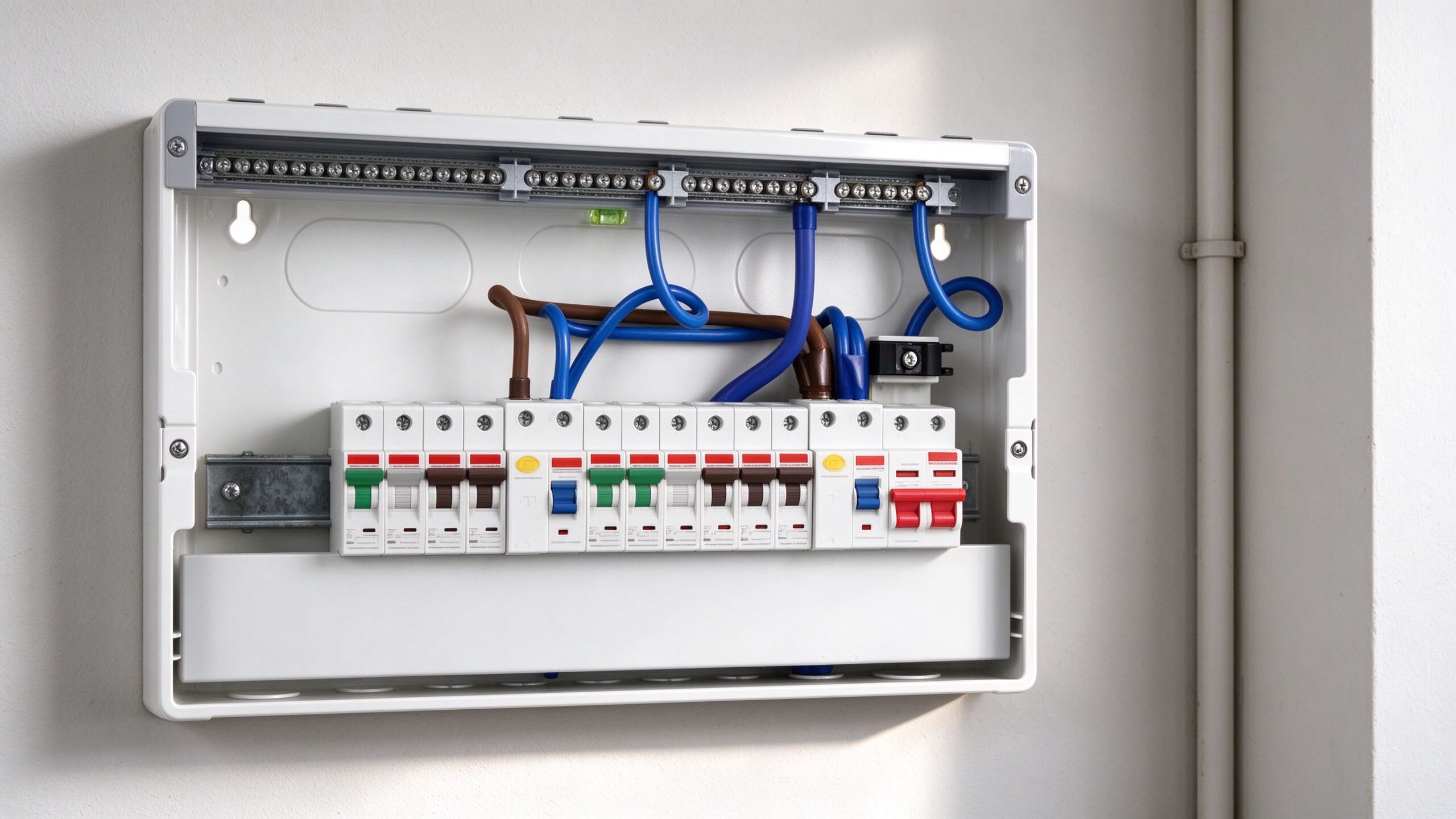
A heating mat is a resistive load, and a resistive load in good condition does not leak. That is the theory, and it is the reason a lot of buyers assume the RCD is ceremonial. In practice, four mechanisms put current where it should not go.
Capacitive coupling through the insulation. A flexible heating element is a conductor separated from an earthed surface by a thin dielectric. Every square metre adds a small capacitance, and 50 Hz alternating current flows through that capacitance continuously. The current is tiny per mat, but it scales with heated area and with the dielectric’s condition. A 12 m² bathroom is not the same electrical object as a 90 m² open-plan floor.
Moisture in the build-up. Screed is not dry on the day the mat is energised. Adhesive under tile, self-levelling compound, grout, and the residual moisture in a timber subfloor all raise the conductivity of the path between the element and earth. This is why a mat that tested clean on installation can trip a device two weeks later when the floor is still drying, and then behave perfectly once the moisture front has passed.
Damaged or damp terminations. The cold lead, the splice, and the joint where the mat meets the supply are the three places where insulation is thinnest in practical terms. A joint that was sealed on a dry day and then sat in a wet screed is a joint with a leakage path. Field measurements on failed installations very often land on the termination rather than the element.
Connected electronics. The mat itself is linear. The thermostat is not. A modern programmable or Wi-Fi thermostat contains a switched-mode power supply, and that power supply can inject a small pulsating direct current component into the protective conductor. This matters for the type of device selected, which we come to below.
The practical consequence: a heating mat’s residual current is not one number. It is a number that depends on area, moisture state, termination quality, and the electronics on the same circuit. A device selected for the dry, ideal case will trip in the real case.
30 mA, 10 mA, 5 mA: Three Devices Doing Three Different Jobs
Buyers routinely compare 10 mA and 30 mA as if one were simply “safer”. They are not on the same scale. They serve different purposes, and the difference in purpose explains why the same project can legitimately need both.
30 mA is additional protection against electric shock. The value comes from the premise that a current of this magnitude, flowing through a person for a short duration, is unlikely to cause ventricular fibrillation in normal conditions. The device is not there to protect the mat. It is there to protect the person who drills into the floor, touches a damaged cold lead, or stands on a wet tiled floor while an appliance fails. IEC 60364-4-41 treats 30 mA as the standard rating for additional protection, and national wiring rules in most of Europe follow it. UK practice under BS 7671 requires 30 mA protection for socket-outlets, for locations with increased shock risk such as bathrooms, and for buried cables that cannot be mechanically protected.
10 mA is a lower threshold for locations where the consequences of a shock are worse or the environment is wetter. It trips at a current a person can still feel but is much less likely to be incapacitated by, and it is sometimes specified in medical, agricultural, and heavily wet environments, and by clients who want a tighter margin on nuisance-free operation in large heated areas. It is also a device that tolerates less cumulative leakage: a 10 mA device protecting six mats with damp screed is a device looking for a reason to trip.
5 mA is the North American Class A ground-fault circuit interrupter threshold. A Class A GFCI is required to trip in the 4–6 mA band, which is roughly one-sixth of the European 30 mA threshold. This is why North American buyers who import European mats sometimes find that a device which behaved on a German project trips immediately on a US installation: the device is doing a different job at a different threshold, and the mat’s normal capacitive and moisture-related leakage, entirely acceptable under a 30 mA regime, is large enough to look like a fault to a 5 mA device.
| Device | Typical threshold | Primary job | Behaviour on a heating mat circuit | Where it fits |
|---|---|---|---|---|
| 30 mA RCD (IEC type) | 30 mA, trip within 300 ms at rated current | Additional protection against shock to persons | Tolerates the normal leakage of large heated areas; trips on real insulation failure and on wet terminations | Standard European residential and commercial floor heating; bathrooms; buried cables |
| 10 mA RCD | 10 mA | Tighter shock protection and lower cumulative leakage tolerance | Trips earlier; needs careful circuit partitioning on multi-mat floors | Wet rooms with high exposure, medical and agricultural areas, client-specified low-threshold projects |
| Class A GFCI (North America) | 4–6 mA | Shock protection at a much lower threshold | Noticeably less tolerant of moisture and capacitance; circuit design must be more conservative | US and Canadian wet locations, bathrooms, kitchens, and heated floor circuits under NEC rules |
Type AC, Type A, Type F: the Letter Matters More Than the Number
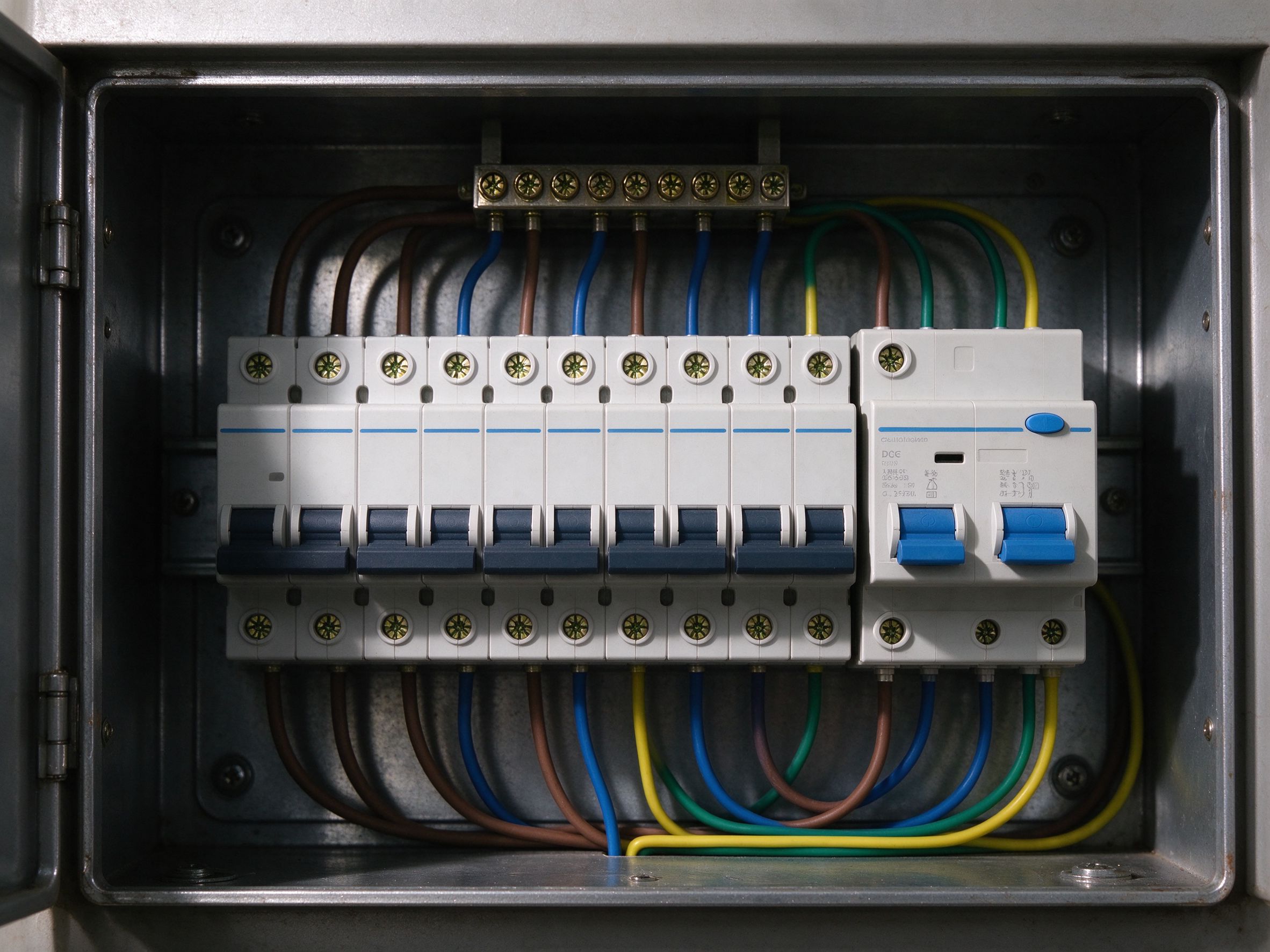
The rating gets all the attention, but the type designation is what determines whether the device can see the fault it is supposed to catch. A 30 mA device of the wrong type is a device that may not trip when it should, and may trip when it should not.
Type AC responds to sinusoidal alternating residual current only. It is the cheapest device, and it is still widely sold. It is also the wrong choice for a circuit whose residual current contains a pulsating direct component, because that component can blind the device to the alternating part it is meant to detect.
Type A responds to sinusoidal alternating current and to pulsating direct current. Any circuit with a thermostat containing a switched-mode supply, a dimmer, or an electronic controller belongs on Type A. On a floor heating circuit, that means essentially every modern installation. The cost difference between Type AC and Type A is small; the failure mode of choosing AC is a device that sits quietly while a fault develops.
Type F adds immunity to mixed-frequency residual current and is used where variable-speed drives or inverter-driven equipment share the installation. A floor heating circuit on its own rarely needs it, but a heating circuit sharing a distribution board with a heat pump inverter or a PV inverter is a different case, and the device type should follow the whole board, not just the mat.
Our recommendation to buyers is simple and unglamorous: specify Type A as the default, and specify Type F only when the same board carries inverter-driven equipment. If a quotation lists “30 mA RCD” without a type letter, the specification is incomplete, and the cheapest compliant-looking device that a contractor can buy will be Type AC.
How Many Mats Can Share One RCD
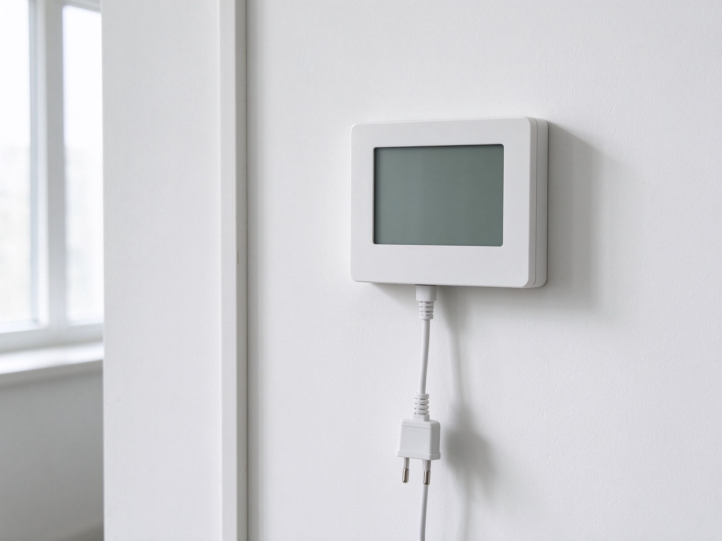
There is no single correct number, because the answer depends on area, moisture state, and the device threshold. What there is, is an arithmetic that too many projects skip.
Add the residual currents. Each mat contributes a small capacitive and dielectric leakage current; each thermostat contributes its electronics’ contribution; each metre of damaged or damp termination adds a path that should be zero. The sum has to sit comfortably below the device threshold, with margin for the wettest day of the first heating season, not the driest day of commissioning.
A workable design rule, and one we apply when sizing our own test benches, is to keep the expected total residual current at or below one third of the device threshold. On a 30 mA device, that is a design target of about 10 mA. On a 10 mA device, about 3.3 mA. On a Class A GFCI, under 2 mA. This is not a standard requirement, it is a margin that absorbs moisture, ageing, and the difference between a laboratory mat and a mat that has been walked on for two years.
In practice, the number of mats per device is governed less by the sum than by three practical constraints:
- Circuit capacity. A 16 A circuit at 230 V carries roughly 3.6 kW. At 150 W/m², that is about 24 m² of heated area per circuit. The RCD follows the circuit, so a 90 m² floor becomes four circuits and typically four devices, or two devices each protecting two circuits.
- Fault isolation. One device per zone means a fault takes out one room, not the whole house. On a retrofit where the client will not accept a cold house in January, this is worth more than the saving on device count.
- Wet-area segregation. Bathrooms, shower rooms, and utility areas with regular water exposure should not share a device with dry living areas. When they trip, the cause is almost always in the wet room, and separating them shortens the diagnosis from a day to an hour.
What Nuisance Tripping Actually Tells You
The single most expensive outcome of a badly specified RCD is not a failed device. It is a heating system the client stops trusting, and a call-back that consumes a day of labour and a replacement mat that was never at fault.
In our experience of warranty enquiries, nuisance tripping on a heating mat circuit resolves into four causes, in roughly this order of frequency:
Moisture in a fresh screed or adhesive bed. The floor is still drying. The device is doing its job. The correct response is to let the build-up dry and re-test, not to replace the device with a higher threshold.
A damp termination. A cold lead joint or a splice that was not sealed correctly, or that sits in a location where condensate collects. The insulation resistance test will show it, and the fix is at the joint.
Cumulative leakage across too many mats. Six mats on one device, each contributing a little, and the total sits within a few milliamps of the threshold. The fix is partitioning, not a bigger device.
The wrong device type. A Type AC device on a circuit with an electronic thermostat, tripping on the pulsating component the thermostat injects. The fix is the correct type, and it is the cheapest fix of the four.
Note what is not on the list: “the mat is faulty”. A genuinely faulty mat, one with a breached element insulation, shows up on an insulation resistance test as a hard, stable, repeatable low reading, and it does not present as intermittent tripping that clears after a dry week.
Selection Framework by Project Type
The table below is the one we use when a buyer asks “what should we put on the drawing”. It assumes European 230 V single-phase supply unless stated. North American projects need the GFCI column substituted for the RCD column, and the circuit arithmetic re-run at 120 V or 240 V.
| Project type | Heated area per circuit | Device | Mats per device | Reasoning |
|---|---|---|---|---|
| Single bathroom, renovation | 3–8 m² | 30 mA Type A, dedicated | 1 | Highest shock exposure in the house; isolation keeps the rest of the floor live |
| Apartment, full floor, dry rooms | 20–25 m² per circuit | 30 mA Type A, one per two circuits | 2–4 | Balances device count against fault isolation; dry rooms tolerate shared protection |
| Large open-plan house, 90–150 m² | 24 m² per circuit | 30 mA Type A, one per zone | 1–2 | Zone-level isolation is the client-visible benefit; cumulative leakage stays far from threshold |
| Wet rooms, spa, pool surround | 10–15 m² per circuit | 10 mA or 30 mA Type A, segregated | 1 | Water exposure raises both shock risk and leakage; segregation shortens diagnosis |
| Commercial kitchen or food prep | 15–20 m² per circuit | 30 mA Type A per area, GFCI in North America | 2 | Wet cleaning cycles; separate from office and retail areas |
| Agricultural and livestock buildings | As per zone | 30 mA Type A, 10 mA where client specifies | Per pen or per house | Dust, ammonia, and washdown; devices in sealed enclosures outside the animal area |
| North American residential | As per 120 V or 240 V circuit | Class A GFCI | 1–2 | 4–6 mA threshold demands conservative partitioning and dry commissioning |
The Nine-Parameter Enquiry Sheet
Most specification errors originate in the first email, because the buyer asks for a mat and the factory quotes a mat, and nobody asks about the circuit. Nine parameters close that gap. We ask for all nine before we release a production slot, and a buyer who supplies all nine gets a quotation that matches what the electrician will actually install.
| # | Parameter | Why the factory needs it |
|---|---|---|
| 1 | Heated area, room by room, in m² | Sets mat quantity, circuit count and total connected load |
| 2 | Target power density, W/m² | Determines element spacing and the mat’s rated wattage; drives circuit arithmetic |
| 3 | Supply voltage and phase | 230 V single phase, 400 V three phase, 120/240 V North America; different element and lead configurations |
| 4 | Device threshold and type required | 30 mA Type A, 10 mA, Class A GFCI; decides how many mats may share protection |
| 5 | Thermostat model and load | Confirms the thermostat’s switching capacity and whether a contactor is needed |
| 6 | Build-up: screed, tile adhesive, self-levelling, or dry-lay | Sets the moisture profile at first energisation and the commissioning delay |
| 7 | Termination environment | Whether the cold lead joint sits in a dry wall box or in a wet floor; drives sealing spec |
| 8 | Certification and documentation set | CE, RoHS, LVD and EMC documentation for the destination market; test reports for the electrical contractor |
| 9 | Quantity, delivery window, and OEM labelling | Production slot, lead time, and whether the mat carries your brand or ours |
Five Specification Mistakes We See on Drawings
1. “RCD by others” with no threshold or type. The item is on the drawing, the responsibility is on someone else, and the device that gets fitted is the cheapest compliant one. Specify the threshold and the type letter, or the specification is not a specification.
2. One device for the whole floor. Convenient on paper, miserable in service. A single fault takes out every zone, and the client’s first experience of the system is a cold house.
3. Selecting 10 mA for “extra safety” without re-running the arithmetic. A lower threshold is a better shock margin and a worse nuisance margin. Choose the threshold first, then partition the circuits to suit it — not the other way round.
4. Ignoring the thermostat’s contribution. The thermostat is a load on the circuit and a source of residual current. A 16 A thermostat on a 3.6 kW circuit is running at its limit, and a thermostat that switches a contactor instead changes the whole protection layout. Our guide to contactor sizing for larger heating loads covers the arithmetic.
5. Commissioning a wet screed on a 5 mA device. The most common North American retrofit failure. The mat is fine, the screed is wet, and the device is doing exactly what a 4–6 mA threshold device does. Delay first energisation, or accept a drying period with the device isolated.
Data and Evidence
SunAura Thermal has manufactured flexible heating elements in Qingdao’s Huangdao district since 2008, and we hold ISO 9001, ISO 14001 and ISO 45001 certification for the quality, environmental and occupational safety systems across that plant. Products for the European market are supplied with CE marking supported by Low Voltage Directive and EMC documentation, and RoHS material compliance declarations. We export to more than 50 countries, and roughly a third of our floor heating volume goes to buyers who specify the electrical protection regime themselves rather than leaving it to the installing contractor.
The electrical figures in this article are drawn from three kinds of source. Thresholds and trip-time behaviour come from the IEC 61008 and IEC 61009 series for residual current devices, and from IEC 60364-4-41 for the principle of additional protection at 30 mA. The treatment of flexible sheet heating elements follows IEC 60335-2-96, which is the product standard covering this class of heater and sets the leakage-current test regime at 1.06 times rated voltage. North American thresholds follow the Class A GFCI definition used in UL 943 and the wet-location requirements of the National Electrical Code. Installation rules cited for Europe follow IEC 60364-7-701 for bathroom locations and, in the UK, BS 7671.
Every mat that leaves our plant is insulation-resistance tested and high-voltage tested before packing, and the test record travels with the shipment so that the electrical contractor has a baseline to compare against on site. That baseline is the single most useful document in a nuisance-tripping investigation: a mat that read clean at the factory and reads clean on site, on a circuit that trips, is a circuit problem, not a mat problem.
FAQ
Does an electric heating mat legally require an RCD? In most European jurisdictions, yes — either because the location type requires additional protection or because the installation rules require it for the circuit. In North America, wet-location and heated-floor circuits require Class A GFCI protection. The safe specification default is 30 mA Type A in Europe and Class A GFCI in North America, with the type letter stated explicitly.
Can I use a 10 mA device to be safer? You can, but you must re-run the circuit partitioning. A 10 mA device with six mats on a damp screed will trip during the first heating season. Lower threshold means fewer mats per device, not more safety per euro.
Is a Type AC device acceptable if the thermostat is a simple bimetallic unit? It is closer to acceptable, because a bimetallic thermostat injects no pulsating direct component. But bimetallic thermostats are now rare in underfloor heating, and the price difference to Type A is too small to justify the risk of a later thermostat change leaving the device blind.
Why does my heating trip the RCD only in winter? Because the floor is wetter, the terminations are colder, and condensate collects where it did not in summer. Seasonal tripping is a moisture signature, not an element failure signature.
Can one RCD protect heating and lighting circuits together? It can, and it is a bad idea. A heating fault then takes out the lights, and a lighting fault takes out the heating. Keep the heating circuits on their own device or device group.
What test proves the mat is not the cause? Insulation resistance at the mat’s cold lead, with the mat disconnected from the circuit, compared against the factory test record. If the reading matches the factory value, the mat is not the fault path.
Do I need a contactor as well as an RCD? They do different jobs. The RCD protects people; the contactor carries load the thermostat cannot. Above roughly 3.5 kW per thermostat, or where the thermostat’s own rating is close to the connected load, a contactor is the correct solution.
Next Step
If you are specifying a heating mat project and want the electrical schedule to match the mat you are buying, send us the nine parameters above. We will come back with a mat selection, a circuit layout, a device recommendation with the type letter stated, and the factory test documentation your electrician will need at handover.
For buyers comparing mat constructions before fixing the electrical design, our electric heating mat range lists the standard sizes, wattages and lead configurations, and the thermostat wiring and sensor placement guide covers the connections that sit between the mat and the device. Buyers procuring at volume can request the RCD and circuit schedule as part of the quotation, so that the protection design and the mat specification are released together rather than a month apart.
Ethan Sun, Founder & CEO, SunAura Thermal