
A Retrofit That Had to Protect the Artwork First
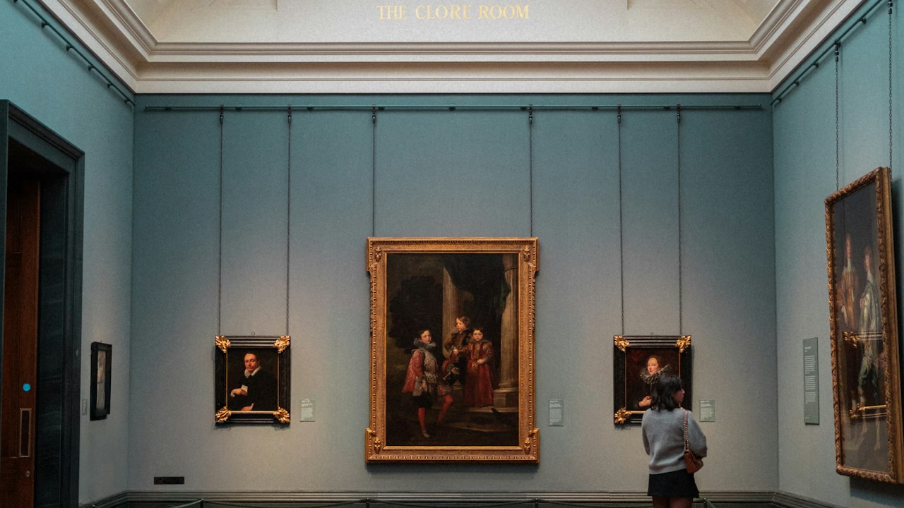
Most floor heating projects are specified against a comfort target. A gallery retrofit is specified against a constraint. When a regional museum planned to convert a nineteenth-century exhibition hall into a year-round display space, the heating system had to meet three conditions that pulled in different directions: hold a stable room temperature to protect the exhibits, avoid the hot surfaces and air movement that damage sensitive materials, and be installed into a historic floor without altering its appearance or structure. This case study traces how the project moved from those constraints to a low-temperature radiant solution, and what the specification decisions mean for similar sensitive-space retrofits.
The Building and the Problem
The hall was a high-ceilinged space with an original stone floor, tall single-glazed windows, and limited distribution capacity. It had been used for seasonal storage and was only intermittently heated, so the existing system could not maintain the steady conditions a curated exhibition requires. The curatorial team set the environmental limits first: a narrow band of room temperature with slow rates of change, controlled relative humidity, and no forced air moving dust across the exhibits. Conventional radiator or ducted systems struggled against all three, because they heat unevenly, cycle on and off, and move air aggressively.
The structural team added a second set of constraints. The floor was listed and could not be raised by more than a few millimetres, the walls could not carry visible services, and the building’s electrical supply had limited headroom for a large connected load. Any solution had to be thin, quiet, distributed across the floor rather than concentrated on a wall, and efficient enough to run within the available supply.
Why Low-Temperature Radiant Heat Fit the Constraints
Radiant floor heating addresses the curatorial constraints directly. Because the heat is emitted across a large surface at a modest temperature, the room reaches an even condition without hot spots, and the system runs with no air movement and no noise. A low-temperature strategy — large heated area, gentle output, long gentle run cycles — produces the slow thermal changes that sensitive exhibits require, rather than the sharp on-off cycling of a radiator system. The floor itself becomes the emitter, which removes the need for visible wall plant.
The choice between element types was driven by the build-up constraint. A wet screed system would have raised the floor too far and introduced moisture into a historic structure, so the project used a thin, low-profile electric mat laid directly over a prepared substrate and finished under a thin compatible layer. The connected load was spread across multiple zones, each switched through a floor-probe thermostat so the surface temperature — the variable that matters most for the exhibits — was directly controlled rather than inferred from the air.
Specification Snapshot
| Parameter | Specification | Reason |
|---|---|---|
| Emitter type | Low-profile electric heating mat | Minimal floor build-up, no wet trades |
| Output strategy | Low density, large coverage | Even low surface temperature, no hot spots |
| Control | Zoned floor-probe thermostats | Direct control of surface temperature |
| Sensing | Floor probe plus room sensor | Surface limit with room setpoint |
| Protection | RCD and insulation resistance test | Safety in a sealed historic floor |
| Run pattern | Long gentle cycles, narrow band | Slow temperature change for exhibits |
| Load split | Multiple small circuits | Fits limited supply, eases balancing |
Installation Sequence in a Historic Space
Survey and preparation
The team began with a full survey of the existing floor, including moisture readings and a record of levels, because any unevenness would telegraph through the thin finish. The substrate was prepared to a flat, dry condition without disturbing the original floor below, and a detailed layout mapped each mat and every cold-lead route before anything was fixed.
Dry layout and test before sealing
The mats were first laid dry and labelled by zone so the team could confirm coverage and avoid cold-lead crossings. Each circuit was tested for continuity and insulation resistance before the finish went down, and the readings were recorded against the zone number. This pre-seal test is the critical checkpoint in a sealed historic floor, where a fault discovered later is expensive to reach.
Control and commissioning
The floor probes were positioned to read a representative area of each zone, away from cold-lead junctions and external influences. Commissioning was deliberately gradual: the system was brought up in small increments over several days rather than run at full output immediately, both to protect the finish and to demonstrate that the room could hold the narrow temperature band with slow change. The final run logged the surface and air temperatures over a full week to confirm stability before the exhibits were installed.
How the Controls Protected the Exhibits
The control strategy did more than maintain comfort; it enforced the curatorial limits. Each thermostat held a floor surface cap, so even if the room called for heat, the surface could never reach a temperature that would create local convection or affect a nearby exhibit. The floor probe removed the lag that air-only sensing introduces in a high-mass historic floor, preventing the overshoot that comes from heating a slab after the air has already reached setpoint. Zoning allowed the perimeter, near the cold single-glazed windows, to compensate independently without overheating the centre of the room.
The result was a room that held a steady condition with gentle, near-invisible run cycles rather than the audible cycling the curators wanted to avoid. The same controls also simplified the handover, because the staff could manage a single room setpoint while the surface limits and zoning operated underneath.
Challenges and How They Were Resolved
Limited build-up. The thin mat and dry preparation kept the floor within the allowed height change, but it left no room for a thick insulation layer. The team addressed heat loss downward through a thin reflective insulation board and accepted slightly longer run cycles rather than raise the floor.
Restricted supply capacity. Splitting the load into small circuits and running a low-density output kept the connected load within the available supply, while the zoned approach meant the full load never switched simultaneously.
Humidity interaction. Raising the temperature of a sealed room can lower relative humidity, so the commissioning team coordinated the heating schedule with the humidity strategy and confirmed the slow ramp did not push the room outside the allowed range.
Irregular floor geometry. The historic hall was not a simple rectangle, so mats were cut and arranged only at the manufacturer’s permitted points and the layout was mapped in advance to avoid weak coverage at the edges.
Seasonal variation. The hall’s heat loss changes sharply between a mild autumn and a cold winter, so the control strategy was verified at both ends of the range rather than at a single mild condition, confirming the room held its band even when the perimeter zones ran for longer. This also let the team set realistic expectations for the longer winter run cycles without changing the surface limits that protect the exhibits.
Data and Evidence
Per SunAura factory records, the low-profile mats and floor-probe controls used in sensitive-space projects are drawn from the same resistance-heating range produced since 2008, with output and tolerance documented against a reference temperature and every circuit subject to insulation resistance and continuity testing before the floor is sealed. The site holds ISO 9001 quality management with CE, RoHS, LVD and EMC documentation. The specific readings in this project — the pre-seal test values, the week-long commissioning log, and the final surface and air temperatures — were recorded against zone numbers and retained in the project file, which is the evidence base that matters for a protected building.
Comfort Heating Versus Conservation Heating
The distinction runs through every decision in a gallery project. Comfort heating is specified around how a room feels to an occupant, and it tolerates short cycles and a moving temperature as long as people remain comfortable. Conservation heating is specified around what the materials can withstand, and it treats stability itself as the target. The governing principle is that rapid change in temperature and humidity is often more damaging to organic materials than the absolute level, so a system that holds a slightly lower but perfectly steady condition is preferable to one that reaches an ideal number through frequent cycling.
This reframes how output is sized. A comfort specification tends to size against the coldest expected day and then controls around it, which can produce a large system that rarely runs at partial load. A conservation specification favours a slightly larger, gentler emitter that runs for long periods at low output, because that pattern delivers the stable condition the exhibits need. The low-density, wide-coverage strategy in this project was chosen for exactly that reason — the system was deliberately not built to spike quickly, but to hold the room in a narrow band with minimal disturbance.
Documentation and Handover for a Protected Building
A retrofit in a listed structure is delivered as much through documentation as through hardware. The project file assembled the as-built layout showing every mat and cold-lead route, the pre-seal test readings against each zone, the commissioning log with the gradual ramp, and a week-long record of surface and air temperatures once the room was holding its setpoint. That file serves two audiences: the conservation team, who need evidence that the environmental limits are met, and any future contractor, who needs to know what sits inside a sealed floor before drilling or fixing anything.
Handover to the museum staff was kept deliberately simple. The team received a single room setpoint to manage, while the surface caps, zoning and run pattern operated underneath without requiring daily attention. They were also given a short schedule of what to monitor — the steady-state readings and any alarm from the protection devices — so that a drift would be noticed early rather than discovered through the exhibits. Lot numbers and the traceability record were included so any component could be traced back to its production run.
Frequently Asked Questions
Can electric floor heating be used in a listed building?
It is often a strong candidate precisely because it is thin, invisible and needs no visible wall services, but approval depends on the build-up and the ability to demonstrate that the original fabric is not altered. Detailed survey and pre-seal testing are the documents that support the application.
Why not use a wet screed system?
Wet systems raise the floor and introduce moisture, which is difficult to reconcile with a historic structure and a tight build-up limit. A dry, low-profile electric system avoids both problems and is simpler to zone and control.
How is the surface temperature kept safe for exhibits?
A floor-probe thermostat enforces a hard surface cap independently of the room setpoint, so the floor cannot reach a temperature that would create local convection or affect nearby materials.
What happens if a mat fails after the floor is sealed?
The pre-seal insulation and continuity tests are designed to make this unlikely, and the zoned layout means a single circuit can be isolated without taking the whole room offline. Lot traceability identifies the source if a fault does appear.
Conclusion and Lessons for Similar Projects
The gallery project shows that in a sensitive-space retrofit, the heating system is specified against the constraints that protect the exhibits — stable temperature, slow change, no air movement, and minimal intervention in the historic fabric — and a low-temperature, low-profile radiant floor meets those conditions more directly than radiator or ducted alternatives. The decisive choices were thin dry construction, a low-density output spread across zones, and floor-probe controls enforcing a surface cap. For any museum, archive or protected-space project, the practical lessons are to specify the environmental limits first, test every circuit before the floor is sealed, and commission gradually with a documented temperature log.
For the control approach, the smart thermostat page explains floor-probe strategy, and the electric heating mat page covers the low-profile build-up used here. The graphene heating film and wall heating film pages set out the wider radiant range for projects where wall surfaces are also available.
Ethan Sun, Founder & CEO, SunAura Thermal