
If you have already read a product page that says “graphene heating film emits far-infrared rays,” you have the marketing version. This article is the engineering version. We are going to open the laminate, look at what the “graphene” layer actually is, discuss why a carbon composite outperforms a single-powder print, and explain how a 45–55 °C wall surface ends up radiating in the 8–14 µm band that human skin reads as gentle radiant warmth. By the end you should be able to pick up any heating-film datasheet and tell whether the numbers on it are real, marketing, or quietly misleading. Written by Ethan Sun, Founder & CEO, SunAura Thermal.
This is not a repeat of the general “how a wall heater works” walkthrough. We assume you already understand that the film turns electricity into heat and radiates it into the room. What we will unpack here is the material layer underneath that: the printed graphene-carbon ink, the polyester substrates, the copper busbars, the silver reflective backing, and the electrical choices that let a 500 W/m² panel hold its surface within 3 °C of uniform temperature across a 50 × 400 cm sheet. That uniformity, not the word “graphene” itself, is what determines whether a wall heater lasts three years or fifteen.
What “Graphene” Actually Means in a Heating Film
Walk into any trade show and you will find booths labelled “100% graphene heating film.” Almost none of them are telling you the whole truth. A single-layer graphene sheet, as produced in the laboratory, is one atom thick and extraordinarily expensive. You cannot screen-print it, you cannot laminate it to polyester, and you cannot economically sell it at 220 V to a homeowner at a price that competes with convection radiators. What every serious manufacturer actually sells is a graphene-carbon composite resistive ink, screen-printed or flexographically printed onto a polyester substrate, with graphene nanoplatelets as one component of a broader conductive network.
The percolation problem
A resistive heating layer has one job: turn a controlled fraction of electrical energy into Joule heat across a large area, evenly. To do that it has to be a conductor, but not too good a conductor. If the layer were pure metal, the resistance would be far too low, the current would be enormous, and the sheet would draw hundreds of amps on a 220 V feed. If the layer were pure insulator, nothing would heat up at all. The usable window sits somewhere in the range of tens to hundreds of ohms per square, and you get there by loading a polymer binder with conductive fillers until the filler particles touch each other and form a continuous path through the film.
That transition is called the percolation threshold. Below it, particles are isolated islands and the film is effectively an insulator. Just above it, a handful of contact points carry the current, the resistance is unstable, and any local defect opens a high-current hotspot. Well above it, the film is a near-short circuit and the wattage runs away. The art of the ink formulation is to sit on the gentle slope just above percolation, where the sheet resistance is stable, repeatable, and insensitive to small print-thickness variations.
Why mix graphene with carbon black at all?
A buyer reasonably asks: if graphene is the star material, why not load the ink with only graphene? Three reasons.
First, cost. Graphene nanoplatelets are far more expensive per kilogram than conductive carbon black. A pure-graphene ink would price the film out of the residential wall-heating market before it even leaves the factory. A well-formulated composite uses a modest fraction of graphene (typically a single-digit percentage by weight of the solid filler) as a “bridge” material, surrounded by cheaper carbon black that carries most of the conductive load.
Second, network architecture. Carbon black particles are roughly spherical. Packed together, they form point-to-point contacts. Graphene nanoplatelets are flat, micron-scale sheets. In the same printed layer, those sheets bridge multiple carbon-black particles at once, shortening the conductive path and dramatically improving the uniformity of the percolation network. The result is a lower sheet resistance for the same filler loading, and a film that stays within tolerance even when the screen deposit varies by a few micrometres across a 400 cm length.
Third, thermal and electrical stability. Carbon black alone in a polymer binder tends to drift in resistance over hundreds of thermal cycles, because the polymer relaxes and the point contacts between spheres re-organise. Adding platelet-shaped graphene anchors the network mechanically; the flat sheets cannot roll or re-arrange as easily as spheres, so the printed stripe holds its resistance better over years of heating and cooling. That stability is what lets us quote a multi-year film warranty rather than a twelve-month punt.
Graphene sheet versus carbon black in practice
It helps to think of the filler network as a road system. Carbon black particles are small round stones scattered across a field. Current has to hop from stone to stone, and any gap in the pebble layer breaks the path. Graphene platelets are flat paving slabs laid on top of those pebbles. A single slab bridges several pebbles at once, so the number of critical point contacts drops sharply, and the network becomes much less sensitive to the local loading density. You get a film that heats evenly even where the print deposit is slightly thinner or slightly thicker than nominal.
This is the reason reputable factories talk about a graphene-carbon heating element rather than a “pure graphene heater.” The element is a composite, and the composite is what delivers the uniformity buyers actually feel on the wall. If a supplier’s datasheet does not mention a carbon component, treat the claim as marketing until they show you the ink composition on a tech call.
Anatomy of the Laminate
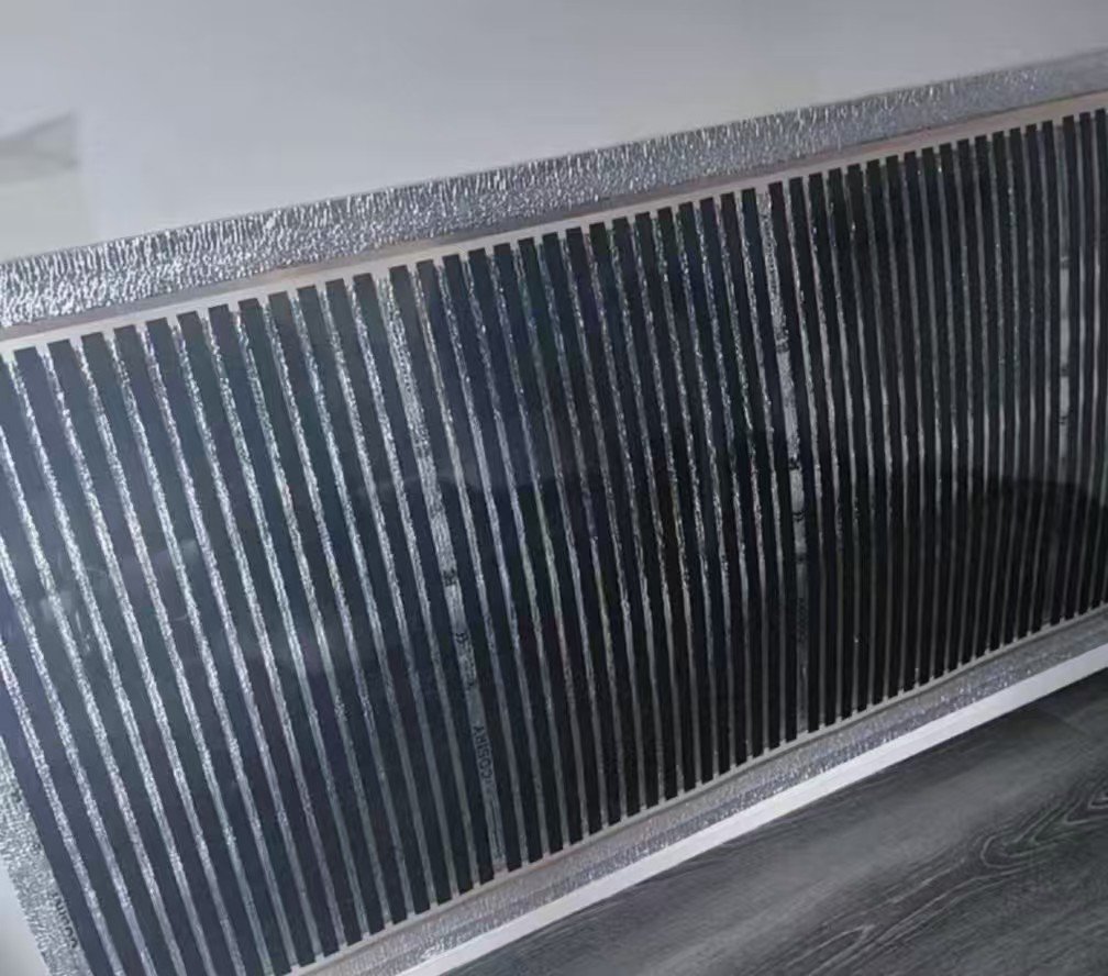
A finished wall heating film looks like a thin grey sheet with a silver border. Cut a cross-section under a microscope and you are looking at a five-layer laminate, each layer chosen for a specific job. Failure modes also tend to be layer-specific, which is why engineers describe failures by layer rather than by “the film broke.”
Layer 1: The polyester base substrate
The mechanical backbone of the film is a polyester (PET) film, typically 25 to 50 µm thick. It is dimensionally stable, it handles sustained surface temperatures of 45–55 °C without creeping, and it is an excellent electrical insulator. The printed ink sits on top of this substrate. The substrate is also what gives the film its tensile strength during shipping, unrolling, and wall mounting. If the substrate is under-specified, the film micro-cracks after a few hundred thermal cycles and the resistance drifts upward, reducing output year over year.
Layer 2: The printed graphene-carbon heating stripe
This is the active resistive layer. It is screen-printed as parallel stripes across the width of the film, typically a few millimetres wide and separated by small gaps. The stripe width, spacing, and ink resistivity together set the power density at 500 W/m² for a 220 V supply. Because every stripe is an independent resistor in parallel, one stripe drifting does not kill the panel; the others keep working. That redundancy is part of why the film tolerates minor installation damage better than a single-element wire heater would.
Layer 3: The copper busbar
At each end of the printed stripes, a copper busbar collects current from every stripe in parallel. The busbar is the most electrically stressed point in the whole laminate: the full panel current flows through it, and any corrosion, oxide layer, or poor mechanical contact shows up as local heating at the edge. On a well-built film the copper is encapsulated between polyester layers and only exposed at the wiring loom. On a cheap film you will see bare copper taped over, which is a corrosion path waiting to happen in a damp room.
Layer 4: The silver reflective insulation backing
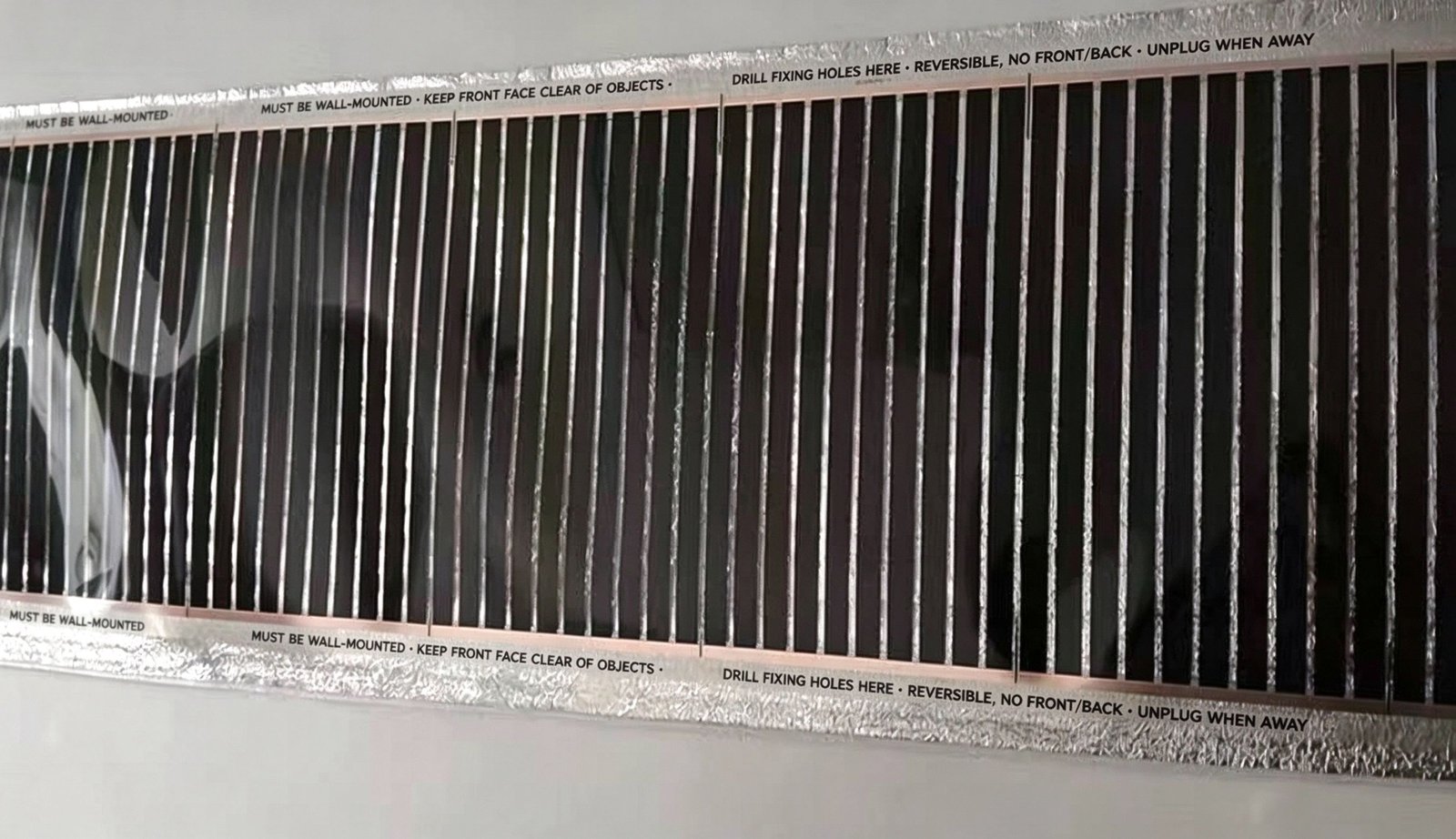
The back face of the laminate is a metallised polyester or aluminium-foil-backed reflective layer. Its job is to stop radiated energy from disappearing into the wall. Without it, roughly half of the emitted infrared would go backwards into the plaster and heat the structure rather than the room. With the silver backing in place, that energy is reflected forward, which is why the front face reaches operating temperature in about a minute instead of slowly warming the wall behind it. The silver border around the edges of the panel is also where factory-printed fixing-hole strips live: you may screw through them, but never through a heating stripe.
Layer 5: The EMI shield
Finally, the construction is fully shielded so that the radiative electromagnetic field of the 220 V resistive element does not escape into the room. This is the feature buyers with nurseries or home offices ask about most. A properly shielded wall heater reads essentially zero electromagnetic radiation in the near field, which is why we can market it as a silent wall heater for bedrooms without fan and without airborne dust circulation. The shield is not part of the heating function; it is a safety and comfort layer, and it is one of the details that separates a finished wall product from a raw industrial roll.
Failure modes map directly onto these layers. PET substrate cracking → localised resistance drift and reduced output. Ink delamination from the substrate → stripe opens up, panel drops wattage. Busbar oxidation → edge hotspot, panel runs hotter at the terminal end. Missing or torn silver backing → energy wasted into the wall, slow warm-up, higher running cost. Shield damage → not a safety trip in normal use, but the bedroom/nursery selling point disappears. When you troubleshoot a film warranty claim, you are almost always diagnosing one of these five layers.
Emissivity and the Far-Infrared Band
The marketing line says “far-infrared heating.” What does that actually mean physically, and why does it matter for a wall surface that only reaches 45–55 °C?
Every surface radiates. Carbon-based surfaces radiate well.
All objects above absolute zero emit thermal radiation. The peak wavelength of that radiation is set by the surface temperature, following Wien’s displacement law: cooler surfaces peak at longer wavelengths, hotter surfaces at shorter ones. A wall at 50 °C sits squarely in the far-infrared region, with most of its energy between roughly 8 and 14 µm. That band is not arbitrary. It is the spectral region where human skin and clothing absorb radiant energy most readily, where the atmosphere is reasonably transparent, and where radiant heating has been used for decades in hospitals, saunas and sports recovery rooms.
How much of the surface’s thermal energy actually leaves as radiation, rather than being reflected internally, is described by the emissivity of the coating. A polished metal surface has low emissivity, often below 0.1, which is why foil makes a good reflector. A matt carbon-based or ceramic-painted surface has high emissivity, typically in the 0.9 range, which is why carbon-film heaters are such effective radiators even at low surface temperatures. The printed graphene-carbon layer on our wall film is a matt, high-emissivity coating; it is designed to dump energy into the room as long-wave radiation, not to reflect it back into the laminate.
The fourth-power relationship you should understand qualitatively
The total radiant power leaving a surface is proportional to the absolute temperature raised to the fourth power (the Stefan-Boltzmann law). You do not need the equation to feel the implication: a small rise in surface temperature produces a much larger jump in radiated output. This is why a 500 W/m² wall film at 55 °C feels noticeably warmer than a 300 W/m² film at 40 °C even though the surface temperature difference looks modest. It is also why covering the front face is dangerous: if the film cannot radiate freely, the surface temperature climbs, and because of the fourth-power law the temperature runaway is not linear. A covered panel can rise past 100 °C in minutes, which is the basis for the safety rule that the radiating front face must stay clear.
We deliberately do not publish a single “emissivity number” on the wall-film datasheet. Emissivity is a measured value that depends on the spectrophotometer, the angle of measurement, and the wavelength band you integrate over; quoting one decimal place out of context invites buyer questions we would rather answer on a technical call. What we will say qualitatively is that the printed carbon surface is a high-emissivity radiator in the 8–14 µm band, and that this is the physical reason the film warms people and furniture directly rather than just heating the air.
Why the 8–14 µm band is the comfort band
You will see infrared heaters sold as “near-infrared,” “mid-infrared,” and “far-infrared.” Near-infrared (below 3 µm) is what a heat lamp or a toaster emits; it delivers intense, directional heat that can feel harsh and dries the skin. Far-infrared (8–14 µm) is the band at which objects absorb energy volumetrically rather than surface-burn, and it is the band associated with the comfortable, even warmth people describe as “sunshine through glass.” A wall heater running at 50 °C cannot produce near-infrared; by temperature physics alone it sits in the far band. That is a feature, not a limitation. It is why the same film that warms a bedroom headboard can also be installed above a child’s bed on the Low setting, and why it is a wall mounted electric heater that competes with convection radiators on comfort rather than on raw temperature.
Electrical Design at 500 W/m²
The numbers on the product page are not pulled out of thin air. 220 V rated, 500 W/m² power density, surface uniformity within 3 °C. Each of those choices follows from a materials and geometry decision.
Why 500 W per square metre
Wall film is a low-surface-temperature radiator. You cannot push more than about 500 W/m² at 220 V without forcing the surface above the comfort and safety envelope. Go to 700 W/m² and the uncovered surface climbs past 70 °C, which is hot to the touch and shortens the PET substrate life. Stay at 300 W/m² and the panel takes forever to reach comfortable output, so you need more square metres of wall. 500 W/m² is the engineering compromise: high enough that a 50 × 200 cm panel delivers 500 W of radiant heat into a 5–7 m² room, low enough that the front face stays in the 45–55 °C thermostat-controlled band, with a typical uncovered surface around 60 °C.
The SKU list follows directly from that density. A 30 × 50 cm panel is 60 W. A 50 × 50 cm panel is 125 W. A 50 × 400 cm panel is 1000 W. Every panel on the factory list sits at the same 500 W/m² design point, so sizing a room is mostly an area calculation, not a per-SKU lookup.
Stripe geometry and busbar layout
The printed stripes run across the 50 cm width, and the copper busbars run along the two long edges. Every stripe is in parallel across the busbars. This geometry has two advantages. First, current on any single stripe is small; even if one stripe develops a partial open circuit, the rest of the panel keeps working at nearly full output. Second, the busbar runs the full length of the panel, so voltage drop along the busbar is small and the temperature from one end of a 400 cm strip to the other stays within tolerance.
Why do panels wider than 50 cm ship as multiple 50 cm strips? Because beyond 50 cm, the busbar becomes too long to keep voltage drop in check without over-sizing the copper. Splitting the width into 50 cm strips keeps every stripe short, every busbar short, and the uniformity target of ≤3 °C achievable. It also means a single damaged strip can be replaced without peeling off the whole wall run.
Why the 3 °C uniformity band matters
A 3 °C temperature spread across a 400 cm panel sounds pedantic until you think about it as an aging metric. Every extra degree at a local hotspot accelerates the polyester substrate’s thermal aging, accelerates ink binder breakdown, and accelerates any corrosion at the nearby busbar. A panel that runs 20 °C hotter in one corner will fail in that corner years before the rest of the panel. A panel that holds within 3 °C across its whole surface ages uniformly, and its rated lifetime is governed by the average temperature rather than by the worst spot.
This is the practical reason buyers should ask for a thermal-imaging photo when they evaluate a supplier. A uniform panel shows up as a smooth grey rectangle on a thermal camera. A cheap panel shows up as bright stripes, bright edges, or a hot corner. Those hot spots are where the warranty claims come from two winters later.
Plug-and-play wiring and the in-line thermostat
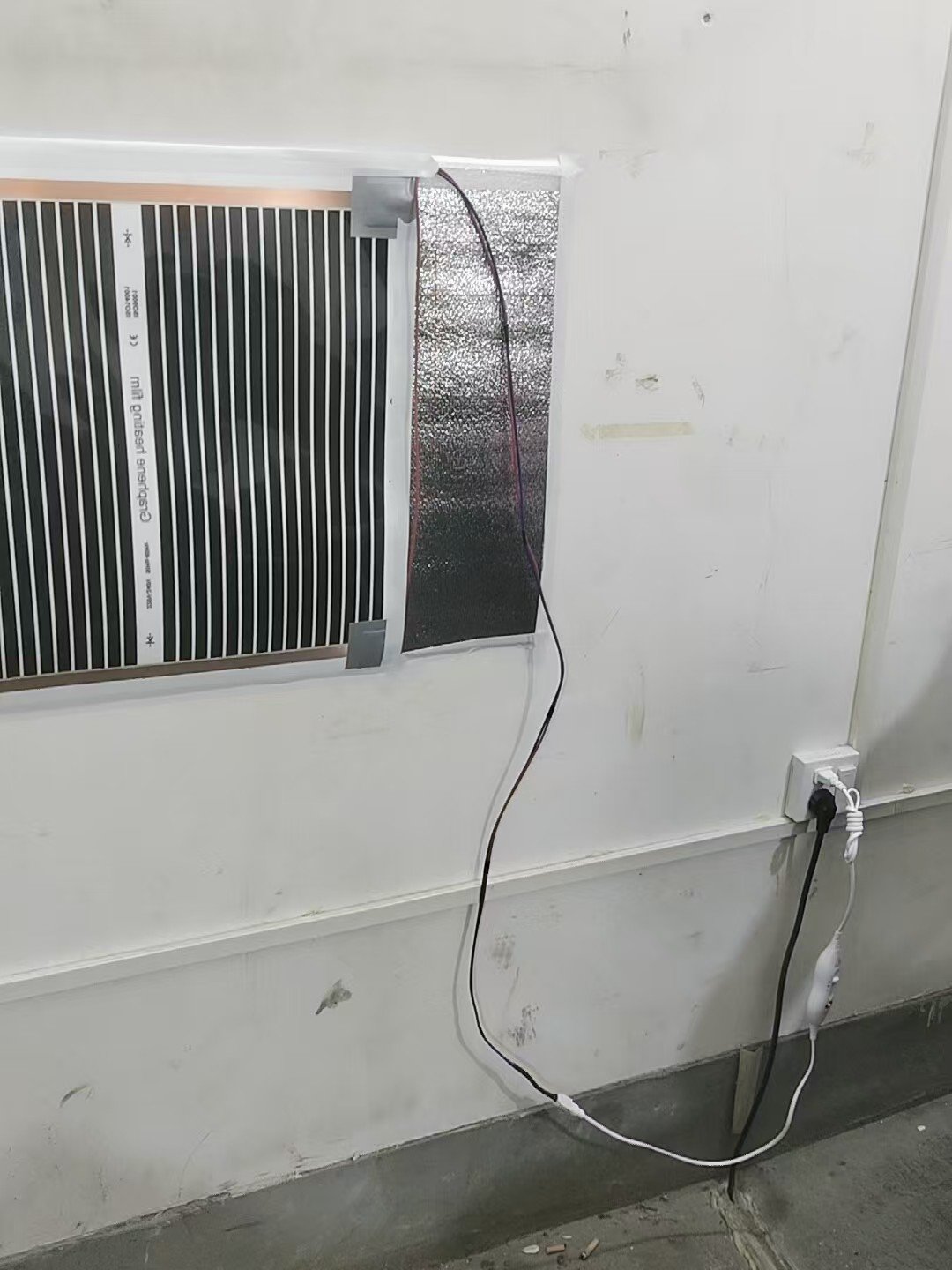
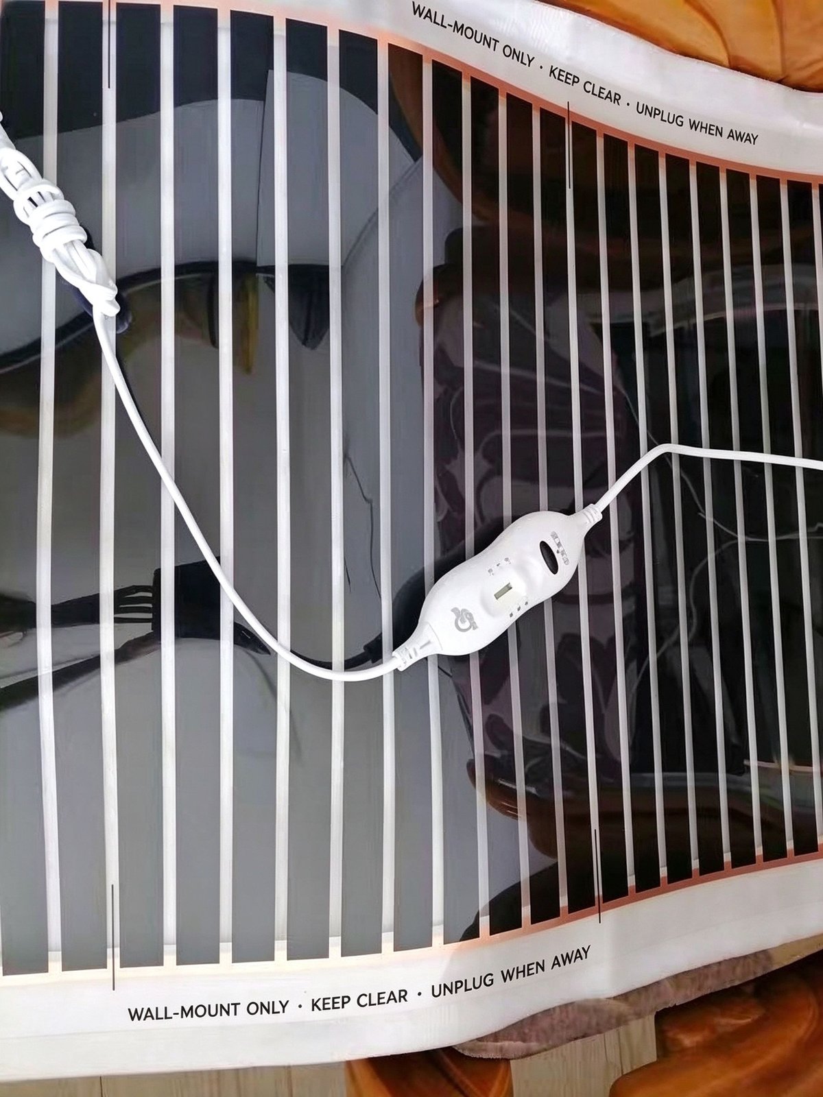
Because the panel wattage is modest (up to 1000 W on the largest SKU), a standard wall socket and an in-line High / Low / Off controller are enough for most rooms. No electrician is needed for retrofit installations, which is a large part of why this product is attractive for rental flats, hospitality refits, and owner-occupied bedrooms. For multi-room projects the same film can be paired with SunAura room thermostats for scheduled, zoned control; the wiring topology does not change, only the controller does. The fully shielded construction means the electromagnetic field at the socket and cable loom is also negligible, which is what makes the product acceptable as a wall heater with no electromagnetic radiation claim in nurseries and sleep labs.
Manufacturing and Batch Control
Material science only matters if the factory can reproduce it every shift. A great ink formula on a screen printer that drifts by 15% between runs is a great formula in the laboratory and a warranty disaster in the field. The SunAura Qingdao plant has been running graphene heating film since 2008, with six automated production lines and an output of roughly 500,000 m² per month, exported to more than fifty countries. Batch control is what lets us quote a multi-year warranty on that volume.
Printing and lamination
The process starts from roll-to-roll PET substrate. The graphene-carbon ink is screen-printed in controlled-width stripes against the registered edge marks. Print thickness, ink viscosity, and screen mesh are monitored every batch; any stripe that falls outside the sheet-resistance window is rejected before lamination. The printed web then goes through thermal curing, which sets the polymer binder and locks the conductive network in place. After curing, the silver reflective backing and the EMI shield are laminated onto the substrate under controlled heat and pressure. Poor lamination is the single most common root cause of long-term delamination claims, which is why we treat the lamination nip as a critical control point rather than a generic packaging step.
Stripe consistency and panel uniformity
Every finished panel comes off the line on a measured length. The 50 cm width is fixed; the length is what sets the wattage, so cutting to the centimetre is part of the electrical design. After cutting, each panel undergoes continuity and insulation checks before the copper busbar loom is crimped and the plug-and-play thermostat is fitted. Panels that fail the continuity test do not leave the line. This is the floor of quality control, not the ceiling; the ceiling is the thermal-uniformity check that samples from each batch and verifies the ≤3 °C spread.
Electrical safety testing under CE/RoHS framework
The factory operates under ISO 9001 quality and ISO 14001 environmental systems, and the wall film is certified to CE and RoHS. We will not quote specific hipot voltages or leakage-current numbers here, because those figures belong on the encapsulated-film datasheet, where the insulation envelope is different. What we will say is that every batch goes through the electrical-safety checks required by the CE/RoHS framework before it ships, and that OEM customers can request the per-batch test reports on their RFQ. For Japanese-market orders, the PSE-related documentation is assembled per order rather than held as a generic document set.
Batch traceability
Because the ink composition is a living formulation — we adjust it slowly over time based on field feedback — every roll carries a batch number. That batch number lets us trace a warranty claim back to the ink lot, the print line, the shift, and the lamination run. Distributors who have been with us for years know that if a panel comes back after three winters, we can tell them which raw-material batch it came from, not just shrug and replace it. That traceability is also what makes the 15-year B2B warranty support framework credible: we have the data to honour it.
Reliability, Aging and Warranty
Buyers ask us how long a wall film lasts. The honest answer is that the film will last a very long time if it is installed and operated within its design envelope, and a disappointing time if it is not. Most warranty claims are installation or operating-envelope failures, not material failures.
What actually ages a heating film
Four mechanisms dominate long-term aging:
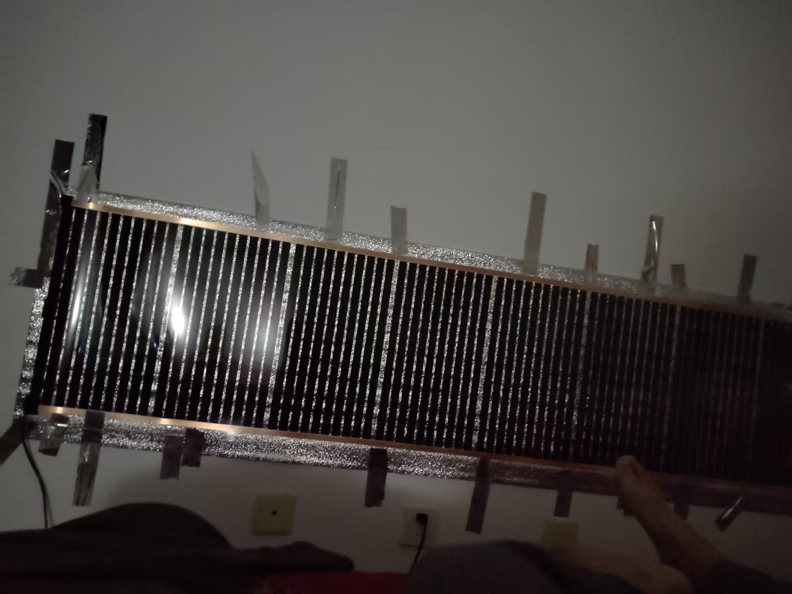
- Delamination. If the laminate edges peel away from the wall, moisture or dust can creep under the film. The substrate still works, but the thermal contact changes and local hotspots can develop. Correct tape and adhesive fixing prevents this.
- Busbar corrosion. Moisture ingress at the wiring loom oxidises the copper. The resistance at the terminal climbs, the terminal heats up, and the panel drops output from one end. This is why the loom must be sealed and why the film is rated for tile-wall bathrooms but not for shower-zone immersion.
- Local hotspots. Any spot that runs hotter than the rest ages faster. The most common cause is covering the front face with bedding, furniture, or cabinetry. The safety rule “wall-mounted, front face clear” exists because covered panels climb past 100 °C quickly.
- Over-temperature operation. Running the film on High 24/7 in an uninsulated room will shorten its life relative to running it on Low for a controlled thermostat schedule. The film is designed for intermittent, thermostat-controlled use, not for full-time industrial bake-out.
Why “wall-mounted, front-face-clear” is the lifetime premise
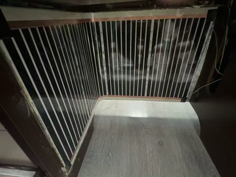
The product page states the safety rules plainly: the film must be wall-mounted, never laid on the floor, under bedding, or inside a cabinet; the radiating front face must stay clear; disconnect when unattended; for nurseries, use Low on an open wall. Those rules are not legal boilerplate. They are the operating envelope inside which the materials are rated. A wall-mounted, uncovered, thermostat-controlled panel runs at its designed 45–55 °C and ages on schedule. A panel tucked behind a sofa cushion or rolled up in a closet runs outside its envelope and will age fast enough that no warranty term will help the buyer.
The warranty, as written
The in-box product warranty is controller 1 year / film body 3 years. That is the consumer-facing number. Behind it sits a company-level 15-year warranty support framework for registered B2B partners, which is the number we quote on distributor and OEM contracts. The difference between the two is not a marketing trick. The consumer warranty covers the plug-and-play product as shipped to a homeowner, where installation quality is outside our control. The B2B framework applies when a distributor or installer works with our application engineers on sizing, mounting, and commissioning, so we can stand behind the panel for much longer. If you are a reseller, ask us specifically about the B2B framework rather than quoting the consumer 3-year number in your own marketing.
How to Read a Heating-Film Datasheet
Every supplier in this category has a datasheet. Most of them omit the numbers that would let you compare fairly. Below is the checklist we hand to our own distributors when they evaluate a competing film. Run a prospectus through these rows before you sign an RFQ.
| Datasheet row | What it should say for a wall film | Red flag if it does not |
|---|---|---|
| Power density | W/m² at rated voltage (we specify 500 W/m² at 220 V) | Only total watts per panel, no W/m² — you cannot compare panel sizes |
| Surface temperature | Operating band and uncovered max (45–55 °C controlled, ~60 °C uncovered) | “Up to 80 °C” — too hot for bedroom/nursery use, substrate life suffers |
| Temperature uniformity | ≤3 °C across the panel at steady state | Not mentioned, or quoted as “even heating” with no number |
| Emissivity / spectral band | Qualitative high-emissivity carbon coating in 8–14 µm far-IR band | A single decimal-place emissivity figure with no method stated |
| Substrate | PET-based polyester laminate | “Polyester” with no thickness or temperature rating |
| Busbar construction | Encapsulated copper busbar, sealed loom | Bare copper taped at edges — corrosion path |
| Shielding | Fully shielded, near-zero EMF | Silent on EMF — ask on the technical call |
| Certifications | CE, RoHS; factory ISO 9001 / ISO 14001 | Self-declared “CE” with no test report reference |
| Warranty | Controller 1 yr / film 3 yr consumer; B2B framework available | “10-year warranty” with no conditions attached — read the small print |
| Coverage guide | Primary vs auxiliary area per panel size | One area figure for all climates — ignores insulation |
Two rows on this table deserve special attention. The first is temperature uniformity. A supplier who can give you a real number (≤3 °C) and a thermal-imaging photo to back it up is a supplier who has measured it. A supplier who only says “even heating” has not. The second is warranty. A 10-year warranty on a film that arrives with a 1-year controller and no traceable batch record is a marketing line, not a service promise. Ask for the warranty terms in writing, ask what voids them, and ask who honours the warranty in your market.
Where Material Claims End
We have spent this article on the material and emission-mechanism story, and it is worth being explicit about where that story stops.
A graphene-carbon composite heating element is genuinely better than a single-carbon-black print at the things this article cares about: sheet-resistance control, stripe-to-stripe uniformity, resistance stability across thermal cycles, and long-term output retention. Those advantages are real and measurable on our own line. They are also advantages that show up most clearly in panels wider than 1 metre, where the tolerance on each stripe matters. On a tiny 30 × 50 cm panel, a cheap carbon film may feel just fine in the first winter. The material advantage is what shows up in year three and year five on a 50 × 300 cm wall run.
What this article has not done is compare a graphene-carbon wall film against carbon-crystal panels, PTC elements, oil radiators, or heat pumps. That comparison lives elsewhere on the site, and it is a different argument: it is about whole-system efficiency, running cost, installation fit, and comfort story. If you want that angle, our related reading on how a graphene wall heater works at the system level covers the installation and use-case side, and our dedicated comparison posts cover the device-class argument. For a look at the rest of the range beyond the wall, browse the graphene home heating series and the custom encapsulated heating film line for projects that need a non-wall form factor.
If you have made it this far, the takeaway is simple. The word “graphene” on a heating film matters, but only in a specific way: it is a platelet-shaped filler inside a printed carbon composite that improves the uniformity and stability of the resistive layer. It is not a magic material, and it does not replace good lamination, good busbar design, good thermal-uniformity control, or honest installation rules. Buy the materials, buy the engineering, and buy the supplier who can show you a thermal camera picture of the panel you are about to order.
You can read the full product specification, the panel size list, and the coverage guide on the graphene wall heating film product page. For wholesale, OEM/ODM, private-label, or multi-room project enquiries, Request Wholesale Price and our applications engineering team will come back with sizing, certification documentation, and a sample lead time for your market.
Frequently Asked Questions
Is a graphene heating film really made of pure graphene?
No, and neither is any commercially sold wall heating film. A pure single-layer graphene sheet is a laboratory material far too expensive to laminate onto a wall panel. Every production-grade film on the market uses a graphene-carbon composite ink: graphene nanoplatelets act as bridging fillers inside a carbon-black conductive network, printed onto a polyester substrate. The graphene improves sheet-resistance uniformity and long-term stability; the carbon black carries most of the conductive load at a viable cost. If a supplier claims “100% graphene,” ask them to show you the ink composition.
What does far-infrared emissivity actually mean on a wall heater?
Emissivity describes how well a surface radiates its thermal energy compared to a perfect black body. A polished metal has low emissivity; a matt carbon-based coating has high emissivity in the 8–14 µm far-infrared band. At a wall-surface temperature of 45–55 °C, that band is exactly where the surface radiates most strongly, and it is the band human skin absorbs comfortably. High emissivity is why a low-temperature wall feels warm to sit near, rather than just heating the air.
Why is the power density 500 W/m² instead of higher?
Push much past 500 W/m² on a wall film and the uncovered surface climbs above the 60 °C comfort and safety envelope, and the polyester substrate ages faster. Stay well below it and the panel takes too long to reach comfortable output, so you need more wall area. 500 W/m² at 220 V is the design point that keeps the surface in the 45–55 °C band, holds the ≤3 °C uniformity target, and lets a 50 × 200 cm panel cover a 5–7 m² room as a primary heat source.
Can I cover the wall film with artwork or furniture?
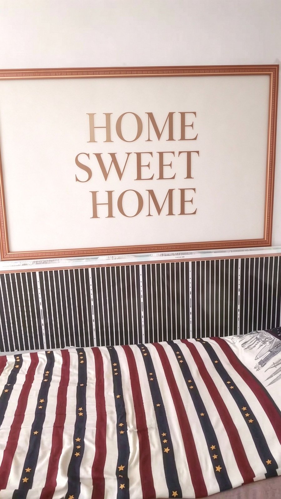
The radiating front face must stay clear. Covering the film traps the radiated energy, the surface temperature climbs past 100 °C quickly, and both the comfort and the lifetime envelope are breached. Artwork and furniture are fine above or beside the panel — many of our most common installations are a film run below a painting or behind a sofa — but nothing should sit directly against the radiating face. For nurseries, install the film on an open wall and run the controller on Low.
How long will the film actually last on my wall?
Inside its design envelope — wall-mounted, front face clear, thermostat-controlled, installed on a suitable interior surface — the film body carries a 3-year in-box warranty, and registered B2B partners work under a 15-year warranty support framework. Outside the envelope — covered, floor-mounted, in a cabinet, or run flat-out on High 24/7 — the film will age much faster and the warranty will not cover it. Most field failures are installation or coverage failures, not material failures.
Do I need an electrician to install a far-infrared wall heater?
For a standard plug-and-play panel up to 1000 W, no. The in-line High/Low/Off thermostat plugs into a standard wall socket, and the film fixes to the wall with tape positioning plus adhesive, with screw fixing allowed only on the factory-printed fixing-hole strips of the silver border. For multi-room projects that pair the film with scheduled zone thermostats, we recommend an electrician for the thermostat wiring, but the film itself remains a retrofit-friendly, wet-trade-free install. It is one of the reasons the product suits rental flats and heritage buildings where wall modifications are restricted.