
Ethan Sun, Founder & CEO, SunAura Thermal
Most heating thermostats fail in the same way: not from a bad sensor, but from a relay that was asked to switch more current than it was built for. A 16 A thermostat is rated at roughly 3,600 W on a 230 V supply. A 20 m² room at 160 W/m² draws 3,200 W. Add a second circuit on the same thermostat and the load sits above 4,000 W. The thermostat still clicks, still shows the right temperature, and slowly welds its own contacts shut over two or three winters. By the time the customer complains, the warranty argument is about “installation error” rather than a component that was mis-specified from the first day.
This is a purchasing problem before it is an installation problem. When you are sourcing thermostats for a project, the question is not “which thermostat looks best in the catalogue” but “how many amps does this zone actually draw, and does that number leave margin”. Getting it right saves the buyer a contactor that was never needed, or a service call that was unavoidable.
Why thermostat load capacity is the first specification, not the last
Electric underfloor heating is a purely resistive load, so the arithmetic is simple and unforgiving. Current equals power divided by voltage. At 230 V, a 3,000 W zone draws 13 A. A 4,000 W zone draws 17.4 A. There is no power factor correction to hide behind and no soft start to smooth the number out.
What complicates the calculation is that thermostats are not rated for their headline current on a continuous duty cycle. A relay rated 16 A for short switching operations is a different device from one rated 16 A for a heating load that stays energised for hours. European switch standards treat heating as a continuous load, and the practical derating used by most manufacturers is around 80 % of the headline figure. That turns a 16 A thermostat into a 12.8 A workhorse, or about 2,900 W at 230 V. Buyers who read the box and stop there are routinely 20 % over the real limit.
The second factor is cold-start current. Constant-wattage cable and heating film are close to purely resistive at every temperature, so their inrush is negligible. Self-regulating cable is not: its cold resistance is lower, so the first seconds after a long off period can pull noticeably more than the steady-state figure. A thermostat sized on the warm-state current of a self-regulating cable can be undersized by a third at switch-on. If your project uses PTC cable, the load figure on the datasheet is the wrong number to design against. Our constant-wattage and self-regulating cable range publishes both the warm-state output and the cold-start behaviour separately, because buyers who only see one figure size the thermostat wrong.
The four control architectures buyers actually choose between
There are only four ways to switch an electric heating zone, and the choice is decided by the load, not by fashion. Each has a different cost and a different failure mode.
| Architecture | Typical rating | Max continuous resistive load at 230 V | Where it fits | Indicative factory price | Main limitation |
|---|---|---|---|---|---|
| Standard thermostat, internal relay | 16 A | 2,900–3,200 W (derated) | Single room up to about 18–20 m² at 150 W/m² | USD 8–16 | Relay is the wear item; no margin for a second circuit |
| Higher-rated thermostat, internal relay | 20 A | 3,700–4,000 W (derated) | Larger single room, 22–25 m² at 160 W/m² | USD 12–22 | Needs a 20 A supply circuit and matching MCB; still one zone |
| Thermostat plus contactor | Thermostat 3 A signal + contactor 25–40 A | 5,700–9,000 W per contactor | Open-plan areas, multiple circuits, commercial floors | USD 22–45 for the pair | Extra DIN rail space, extra wiring, one more component to label |
| Multi-zone controller plus contactors | Controller 3 A per channel + slave contactors | Scales by contactor count | Whole-building retrofit, 6–20 zones | USD 60–180 for the control layer | Commissioning time; needs a wiring schedule the installer will actually read |
The dividing line sits around 3,000 W. Below it, a standard thermostat is the honest answer and adding a contactor is money spent to solve a problem that does not exist. Above it, a contactor is not an upgrade, it is the correct circuit. Between 2,900 and 3,600 W the decision depends on duty cycle and on whether the zone is the only load on that thermostat.
How to size a zone before you open the catalogue
The sizing sequence takes about five minutes per zone and prevents most of the returns we see. Work in this order.
Step one: establish the installed power, not the room area. Multiply the heated area by the design power density. A 16 m² bathroom at 160 W/m² gives 2,560 W. A 24 m² kitchen at 150 W/m² gives 3,600 W. Do not use the floor area of the room; use the area actually covered by mat, cable or film, which is usually 70–85 % of it because of units, door swings and fixed furniture.
Step two: derate. Divide the installed power by 0.8 to see what the thermostat has to be rated for on a continuous basis. The 3,600 W kitchen becomes 4,500 W of required rating, which no internal-relay thermostat will carry honestly. If the design setpoint is still open at this stage, fix it first: our notes on floor and air setpoints by room type explain why a higher setpoint quietly raises the load you are sizing for.
Step three: check the supply circuit. A 16 A thermostat belongs on a 16 A circuit with 2.5 mm² conductors. Putting a 20 A thermostat on a 16 A MCB means the breaker trips before the thermostat is stressed, which is safe but confusing for the occupant. The protection device and the switch have to agree.
Step four: count the zones, not the rooms. An open-plan living area with a kitchen island is often two heating circuits on one thermostat, because the mat runs are separate. Two circuits of 2,000 W each on one 16 A thermostat is a 4,000 W load on a device rated for 2,900 W continuous. This is the single most common mis-specification in residential retrofit.
When a contactor is genuinely required, and when it is not
Buyers often ask for a contactor as insurance. It is the right answer in five situations and the wrong answer in three.
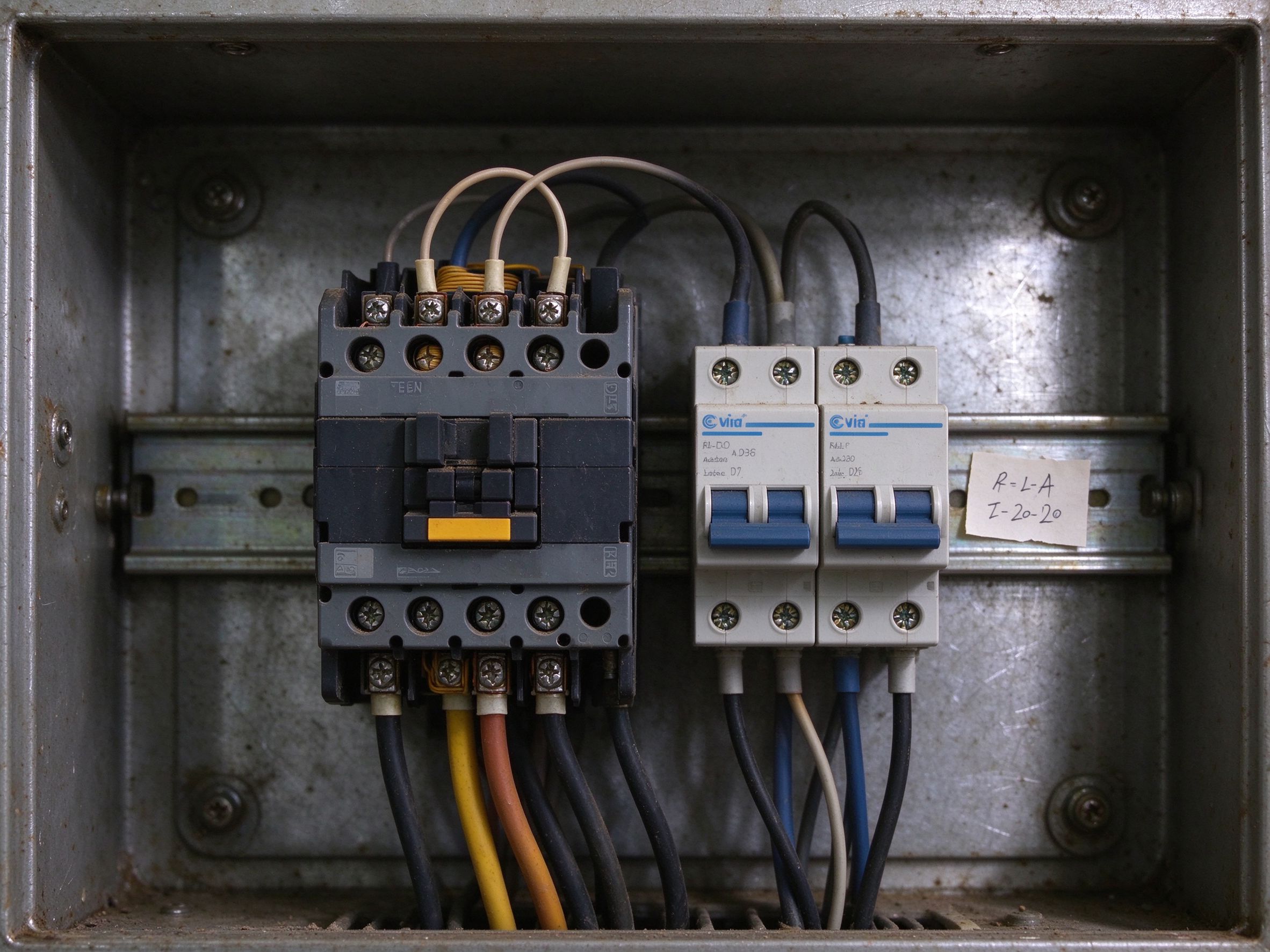
A contactor is required when the total switched load exceeds the derated capacity of the thermostat; when one thermostat controls more than one heating circuit; when the zone exceeds roughly 25 m² at 150 W/m²; when the project uses self-regulating cable whose cold-start current exceeds the thermostat rating; and when the thermostat is mounted in an enclosure where heat from its own relay has nowhere to go, as happens in small wall boxes in warm plant rooms.
A contactor is not required when the load is comfortably inside the derated rating, when the zone is a single small bathroom, or when the “contactor” being proposed is really a way to avoid calculating the load. Adding a contactor to a 1,800 W bathroom circuit adds a failure point, a DIN rail slot and a wire the next electrician has to trace, in exchange for nothing.
For buyers specifying our controls, the K5 series thermostat is a 16 A unit with an external floor probe and a rated continuous load that we publish rather than bury. Where the project needs more, the controller drives a slave contactor and the thermostat never sees the heating current at all. That division of labour is what keeps a 15-year-old installation still switching cleanly: the device that decides is not the device that carries the amps.
What this looks like on a real bill of materials
Consider a 120 m² ground floor with 96 m² of heated area at 150 W/m², giving 14,400 W total.
A buyer who specifies four 16 A thermostats, one per room, is at 3,600 W per thermostat in the largest room, which is above the derated limit and will fail early. The corrected specification is three 16 A thermostats for the small rooms, all comfortably under 2,900 W, and one thermostat plus a 32 A contactor for the open living area, where the load is 6,000 W. The parts cost moves by roughly USD 15. The service cost avoided is a relay replacement visit plus a call-out, which in most European markets starts at USD 90 and rarely stops there.
For a commercial floor of 400 m² at 140 W/m², the total is 56,000 W. At that scale nobody switches the load through a room thermostat. The design becomes a multi-zone controller with one contactor per 6–8 kW group, and the thermostats become sensors with a 3 A output. The purchasing question shifts from “how many thermostats” to “how many contactors and how much DIN rail”, which is a different conversation and a different budget line.
Specification checklist before you send the enquiry
Send these eleven items to a supplier and you will get a quote that can actually be built, instead of a price for a thermostat that may or may not survive.
- Total installed heating power per zone, in watts, calculated from covered area and design density.
- Supply voltage and phase, single or three-phase, and the nominal frequency.
- Number of heating circuits per thermostat, and whether they are wired in parallel at the thermostat terminals.
- Heating element type: film, mat, constant-wattage cable or self-regulating cable, because only the last one needs cold-start current in the sizing.
- Required thermostat rating after derating, expressed in amps rather than watts.
- Whether the thermostat must switch the load directly or drive a contactor.
- Sensor type and cable length: internal air sensor, external floor probe, or both.
- Mounting standard: 86 mm box, 60 mm European box, or DIN rail inside a panel.
- Control protocol needed: relay dry contact, 0–10 V, or a building management interface.
- Ambient conditions at the mounting point, especially in plant rooms and cabinets.
- Whether the project requires the contactor and thermostat to be supplied as one matched pair with a single warranty.
Five specification mistakes we see repeatedly
Sizing on room area instead of covered area. A 20 m² room with a 16 m² heated area is a 2,400 W load at 150 W/m², not 3,000 W. Sizing on the room area pushes buyers into contactors they do not need, and sometimes into the wrong circuit protection.
Reading the headline amps as a continuous rating. The box says 16 A. The continuous heating load it can carry is closer to 12.8 A. Buyers who skip the derating end up 20 % over the real limit on every zone.
Ignoring cold-start current on PTC cable. Self-regulating cable can draw well above its steady-state current in the first minute. A thermostat sized on the warm figure will be stressed at every switch-on, which is exactly when relays wear fastest.
Assuming a bigger thermostat replaces a contactor. A 20 A thermostat buys about 700 W of extra headroom over a 16 A unit. It does not turn a 6,000 W zone into a single-device job, and it does not solve a multi-circuit layout.
Forgetting that the thermostat is also a sensor. A thermostat mounted above a radiator, or inside a cabinet next to a contactor, reads the wrong air temperature and runs the floor hotter than the setpoint. Capacity and placement are the same decision.
So which one should you specify
Under 2,500 W per zone, a standard 16 A thermostat with an external floor probe is the correct and cheapest answer. Between 2,500 and 3,200 W, a 16 A thermostat still works if it is the only load and the mounting point is cool, but the margin is thin and the buyer should expect a shorter relay life. Between 3,200 and 3,600 W, move to a 20 A unit only if the supply circuit supports it; otherwise contactor. Above 3,600 W, a contactor is mandatory and the thermostat becomes a 3 A signal device. Above 10 kW, the conversation is no longer about thermostats at all: it is about a controller, a bank of contactors and a wiring schedule.
If you are buying for a mixed project with small bathrooms and one large open area, the cheapest robust answer is usually one thermostat family across the site, with contactors added only where the load demands it. Uniform spares, one wiring convention, one probe type. That is worth more over a ten-year building life than the few dollars saved by mixing three thermostat models to squeeze under a contactor on one zone.
Data and evidence
The load figures in this article follow the arithmetic of resistive heating at 230 V and the continuous-duty derating convention used across European switchgear documentation, including EN 60669-2-1 for switches intended for household and similar fixed electrical installations. Circuit protection references follow IEC 60898-1 for miniature circuit breakers. Where we describe thermostat behaviour, the figures come from SunAura factory records: every thermostat batch is load-tested at rated current before shipment, and the continuous rating we publish is the derated value rather than the headline relay rating.
Company background, for buyers who need it: SunAura Thermal has manufactured heating film, mat, cable and controls since 2008, operating from the Qingdao (Huangdao) plant under ISO 9001, ISO 14001 and ISO 45001, with CE, RoHS, LVD and EMC documentation for the product lines and distribution into more than 50 export markets. We do not publish certificate numbers in marketing copy; buyers receive the current documentation with the quotation.
FAQ
Can I run two heating mats on one 16 A thermostat? Only if the combined derated load stays under about 2,900 W. Two 10 m² mats at 150 W/m² total 3,000 W, which is already at the edge. Two 12 m² mats at 160 W/m² total 3,840 W and need a contactor.
Does a 20 A thermostat need a 20 A breaker? Yes. The protection device must not be smaller than the switch rating, or the breaker becomes the de facto limiter and nuisance trips follow. Conductors must be sized for the circuit current as well.
Why do thermostats fail at the relay rather than the sensor? Because the relay carries the full heating current for hours at a time, while the sensor only reads a resistance. Relay contacts erode, weld or develop high resistance; the temperature sensing side usually outlives them by years.
Is a contactor worth it on a 3,000 W zone? Generally no. A 16 A thermostat at 3,000 W is at the derated limit but still within it, provided it is the only load on the device and mounted where it can shed heat. The contactor becomes worthwhile when the zone grows or a second circuit is added.
Can one thermostat control a whole floor with several circuits? It can if the circuits are paralleled at the thermostat and the total stays inside the derated rating. In practice that limits a single thermostat to about 2,900 W, which is one medium room, not a whole floor.
Next step
If you are specifying controls for a project, send us the per-zone wattage list rather than a room count. We will return a matched thermostat and contactor schedule, including which zones can run direct and which need a slave contactor, and quote the pair with a single warranty. Start from the K5 thermostat specifications if you want the baseline ratings, or read our notes on floor probe calibration before you fix the sensor position, since a correctly sized thermostat on a badly placed probe still runs the floor wrong.