
What Is a Floor Probe and Why Does Its Position Matter?
A floor probe is a small temperature sensor, usually a thermistor or RTD, that sits inside the floor and tells the thermostat the actual temperature of the floor surface zone. The thermostat uses that reading to control the heating: when the floor reaches the set temperature, the system switches off; when it cools, the system switches on again. The probe is the only device in the system that measures the thing the user actually feels — the floor — which is why its position and calibration decide whether the room is comfortable, whether the floor stays inside the flooring manufacturer’s limits, and whether the system wastes energy short-cycling. A thermostat with perfect software and a badly placed probe will behave badly; a well-placed probe with a modest thermostat will behave well.
Calibration here means more than factory accuracy of the sensor itself. In practice, thermostat floor probe calibration is the combination of three things: the sensor’s electrical accuracy, its physical position relative to the heating elements, and the way the thermostat applies the reading (the set-point offset and hysteresis). Installers who skip any one of the three end up chasing symptoms — a floor that never reaches comfort, a floor that overshoots, or a thermostat that clicks on and off every few minutes. This article explains the physics of each factor, gives the installation rules that make calibration automatic, and lists the field checks a service engineer should run when a customer reports a cold floor or a short-cycling system.
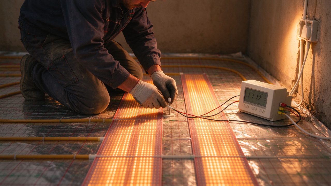
How the Probe Reading Controls the System
Electric floor heating thermostats run in one of two control modes. In floor-sensor mode, the thermostat regulates to the floor temperature: you set 26 °C, the probe reads the floor, and the system modulates to hold 26 °C at the sensor. In air-plus-floor mode, the thermostat manages the room temperature using the floor probe as a limit — for example, heating to 21 °C room air but never letting the floor exceed 27 °C. The second mode is common with flooring that has a maximum surface temperature, because it delivers room comfort while protecting the floor covering. Either way, the probe’s reading is the control variable, and the control variable is only as trustworthy as the sensor’s installation.
The temperature gradient in a heated floor is steep. Directly above an element, the temperature is at its peak; a few centimetres away, between element runs, it is measurably lower; at the surface, it depends on the covering and its insulation. A probe placed directly on an element will read the hottest point in the floor — often 5–10 °C above the surface temperature — and will switch the system off early, leaving the surface cold. A probe placed too far from the elements reads the coldest path and keeps the system on too long, overshooting the surface. The installation rule is simple and absolute: the probe must sit in the gap between two element strips, in the same material layer that will be heated, and never directly on an element. This single rule prevents most calibration problems before they start.
The Three Checks That Make Calibration Automatic
Calibration becomes automatic when three checks are done at installation time. First, the sensor check: before the floor is closed, measure the probe resistance at room temperature and compare it with the sensor’s datasheet curve — a thermistor at 20 °C should read close to its nominal resistance, typically 10 kΩ or 15 kΩ depending on the type. Second, the position check: confirm the probe tip is centred between element strips, not touching an element, and that the lead is routed in a protective sleeve from the probe to the thermostat so a damaged element cannot short into the sensor circuit. Third, the wiring check: the probe must be wired to the correct thermostat terminals — mixing up the probe and the room sensor inputs is one of the most common field errors, and it produces exactly the “thermostat reads nonsense” complaints that end up in service calls.
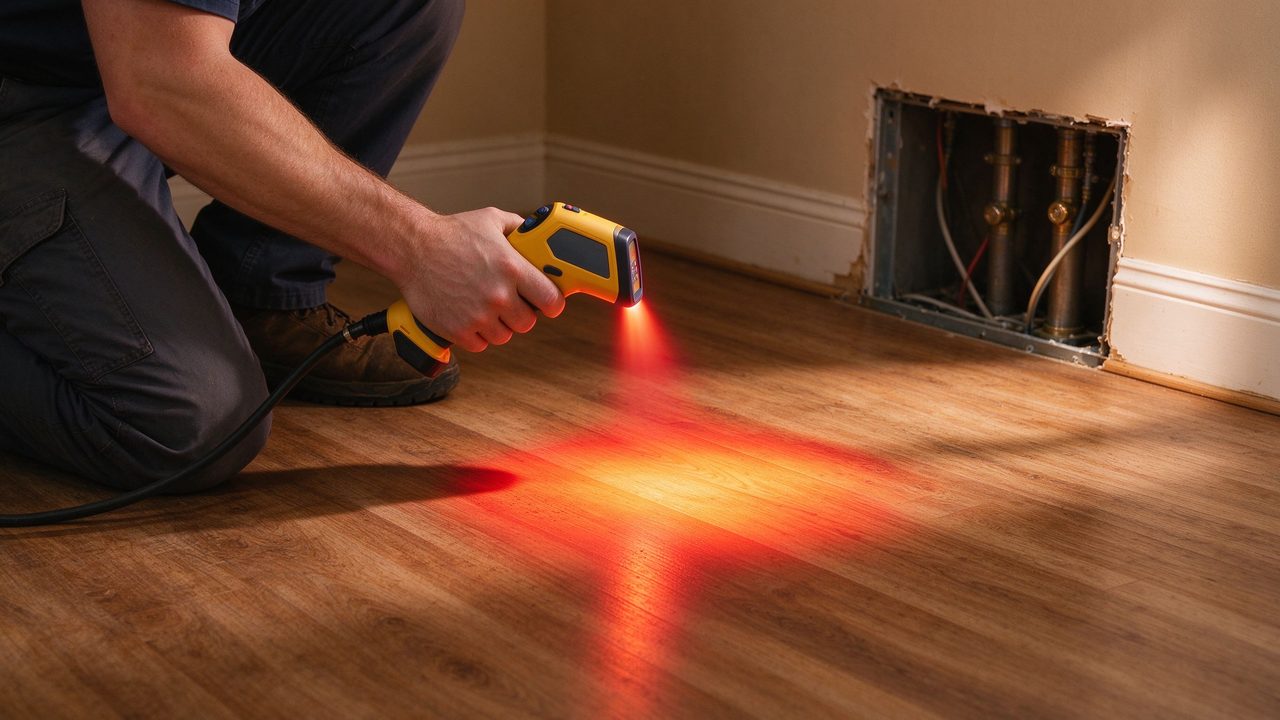
After commissioning, the practical verification is simple: run the system, wait for the floor to stabilise, and compare the thermostat’s displayed floor temperature with an independent floor thermometer or an infrared thermometer at the surface, with the reading taken away from the probe’s position and away from element lines. A difference of more than 2–3 °C suggests a position or insulation problem worth investigating. This verification is the same one our factory documentation recommends for every installation and is part of the commissioning sheet our export team provides with commercial projects (per SunAura factory records).
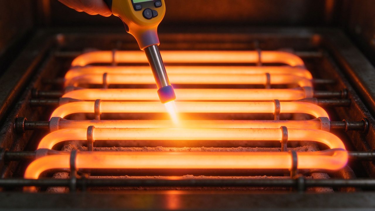
Common Field Faults: Cold Floors and Short-Cycling
Two complaints dominate service calls, and both trace to probe problems. The first is the cold floor: the thermostat shows the floor “at temperature”, but the room is cold. The usual cause is a probe on or too near an element, reading a local hot spot while the rest of the floor stays cool; the thermostat switches off early and the surface never reaches the set temperature. The second is short-cycling: the system clicks on for two minutes, off for two minutes, all day. This is the classic signature of a probe picking up a local hot spot with poor thermal contact — the sensor sits in an air pocket or against an element, so the reading swings violently. The fix in both cases is the same: relocate the probe into the gap between elements, embed it in the layer with good thermal contact, and re-verify with the independent thermometer.
A third, quieter fault is drift over years. Sensors age slowly, and a probe whose insulation has cracked or whose lead has been damaged by foot traffic can drift out of specification. Most thermostats include a probe-fault alarm (an open or shorted sensor is detected automatically), but a drift fault inside the working range is silent. That is why a maintenance visit should include the same three checks run at installation — resistance against the datasheet, position confirmation, and an independent floor temperature comparison. This routine turns underfloor heating sensor calibration from a one-time event into a 15-minute maintenance item with a measurable result.
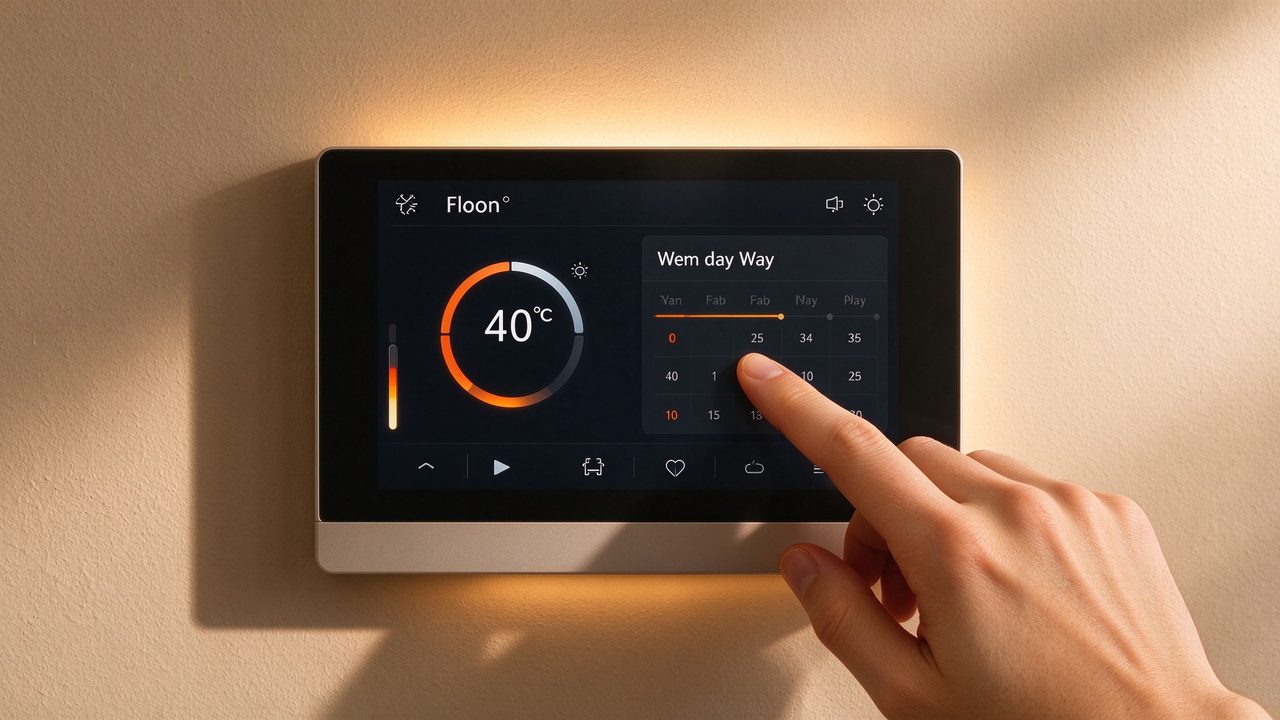
The Set-Point and Hysteresis Side of Calibration
The thermostat software is the third leg. Modern thermostats allow a floor set-point offset, which compensates for the difference between the probe temperature and the surface temperature — the offset number is not a bug, it is a calibration constant for the build-up. A thermostat with hysteresis control switches on at set-point minus hysteresis and off at set-point plus hysteresis; too small a hysteresis with a fast-reacting film floor causes hunting, too large a hysteresis causes temperature swings. The field rule is to set hysteresis around 1 °C for floor control and to use the offset only after the independent surface verification shows a consistent difference. A thermostat accuracy cold floor complaint is very often a set-point offset of zero applied to a build-up that needs +2 °C, or a hysteresis set for an air thermostat applied to a floor probe.
There is also a scheduling interaction. A floor probe reads the floor, and the floor has thermal mass: it takes time to heat and time to cool. A thermostat that ramps the set-point in steps during the pre-heat window uses the probe reading to avoid overshooting the surface temperature while the slab is still absorbing heat. This is why the pre-heat schedule matters for both comfort and flooring protection — a long, gentle pre-heat keeps the surface inside the flooring limit, while a hard switch-on can spike the surface above it. The floor probe is the instrument that makes the gentle pre-heat possible, which is one more reason its calibration is not a minor detail.
Data and Evidence: What a Calibrated System Should Show
A calibrated system produces measurable evidence. The commissioning record should contain: the probe resistance at ambient temperature against the datasheet, the measured floor surface temperature against the thermostat display, and the hysteresis settings applied. During the first full heating cycle, the surface temperature should rise smoothly and hold within the flooring manufacturer’s limit. Our factory specifies probe types and wiring conventions for the complete thermostat range, and the production line — 17 years of heating element and control manufacturing at our Huangdao plant in Qingdao, China, under ISO 9001, ISO 14001 and ISO 45001, with CE, RoHS, LVD and EMC certification, exporting to more than 50 countries (per SunAura factory records) — tests each thermostat’s sensor input before shipment. The test record is available on request, because calibration evidence is part of the product, not a favour.
For a buyer comparing suppliers, the calibration question is a good filter: ask how the supplier tests the sensor input, what probe types are supported, and whether the installation documentation includes the position rule. Suppliers who cannot answer in writing are selling components; suppliers who document the answer are selling a system. That distinction is exactly what the commissioning file and the maintenance routine depend on.
Frequently Asked Questions
Where exactly should the floor probe be installed? In the gap between two element strips, embedded in the same layer that will be heated, never directly on an element, with the lead in a protective sleeve to the thermostat.
How do I know if the probe is reading correctly? Run the system to stabilisation, then compare the thermostat’s floor reading with an independent thermometer at the surface; a difference under 2–3 °C with the system stable is normal.
Why does my floor stay cold when the thermostat says it is at temperature? The classic cause is a probe on or near an element reading a local hot spot and switching the system off early; relocate the probe between elements and re-verify.
What is a floor probe offset? A thermostat setting that compensates for the difference between the probe temperature and the actual surface temperature of the build-up; it is set after an independent surface measurement shows a consistent difference.
Can a faulty probe be replaced without lifting the floor? Usually yes, if the probe is installed in a protective sleeve: the old sensor is pulled out through the sleeve and a new one pushed in. Sleeves are the reason the wiring rule matters at installation.
Sourcing Thermostats with Reliable Floor-Probe Control
For installers and distributors building a reliable control range, the specification should include a real floor-probe input, documented sensor types, and installation guidance that states the position rule. Our thermostat range supports floor-sensor and air-plus-floor modes, with floor probe thermostat wholesale supply for volume programmes and OEM branding. As a thermostat supplier for underfloor heating, we provide the probe, the wiring conventions and the commissioning sheet together, so the calibration routine is documented from day one. Contact our Qingdao export team for the thermostat datasheets and probe specification.
How to Run a Field Verification in 15 Minutes
Service engineers and maintenance teams can verify a floor-probe system in a short, repeatable routine. Step one: confirm the thermostat is in floor-sensor or air-plus-floor mode and note the set-point and the displayed floor reading. Step two: measure the probe resistance at the thermostat terminals with the power off, and compare it with the sensor datasheet — a 10 kΩ thermistor at 20 °C reading below 8 kΩ or above 12 kΩ is suspect, and a reading that jumps when the lead is flexed points to a damaged cable. Step three: with the system running and stabilised, measure the surface temperature with an infrared thermometer in three places away from element lines and compare with the display; a consistent offset is the number to correct in the thermostat’s offset setting. Step four: check the wiring — probe terminals, room sensor terminals, and the protective sleeve condition where the lead enters the floor. Four steps, fifteen minutes, and the outcome is a documented calibration state.
This routine is exactly what our technical documentation recommends for annual maintenance, and it is included in the commissioning sheets supplied with our thermostat range. The value is not just comfort: a calibrated system holds the floor inside the flooring manufacturer’s temperature limit, which protects the floor warranty, and it avoids the energy waste of a short-cycling system. For a maintenance contractor, the 15-minute check is also a commercial opportunity — it converts a vague “check the heating” call into a documented service with a measurable result, which is the kind of work that builds repeat business.
Related Products & OEM Inquiries
Looking for a thermostat with reliable floor-probe accuracy or a factory-direct OEM/ODM partner? Explore our smart thermostats and floor-sensing controls, then request a quote for your project — we supply distributors, installers and brands in 50+ countries.