
Underfloor Heating Temperature Settings: Floor and Air Setpoints for Every Room Type
Most underfloor heating complaints are not caused by a weak system. They are caused by a thermostat setpoint that was chosen by feel rather than by the floor covering, the room use and the standard behind the limit. A floor held at 35 °C will feel wonderful in a tiled bathroom and will wreck a laminate floor in one winter. A floor held at 22 °C will protect the laminate and leave the bathroom feeling cold underfoot. Neither outcome is a product failure; both are setting failures.
This guide is written for buyers and installers who need to specify setpoints before the floor is laid, and for homeowners who want to know what number belongs on the thermostat and why. It covers the three temperatures that matter (air, floor surface and, in wet systems, flow water), the legal and standards-based limits that cannot be exceeded, a room-by-room setpoint table, a comparison of the system types that most often meet those limits, a procurement checklist, and the mistakes that turn a good system into a complaint.
Three different temperatures, and why confusing them causes trouble
When someone says “the underfloor heating is set to 28”, they could mean three different things, and the difference matters enormously:
Air temperature is what a room thermostat measures. It tells the system when the room has reached comfort and is the normal control signal in a well-designed installation.
Floor surface temperature is the number that damages or protects the floor covering. It is limited by the covering manufacturer, by the screed and by the standard governing the heating system. This is the number that must never be exceeded, regardless of what the room wants.
Flow water temperature applies to hydronic systems and to the design of the heat source. A well-designed wet underfloor system runs at 35–45 °C flow for modern insulation levels, which is why heat pumps pair well with it. Electric systems have no flow temperature, but they do have an element surface temperature that behaves in a similar way.
The classic failure is a thermostat controlling on air temperature alone with no floor probe, in a room with a heat-sensitive floor. The room reaches setpoint slowly because the floor is a large thermal mass, the thermostat keeps calling for heat, the floor surface climbs well past the covering limit, and the floor fails. Every credible underfloor installation therefore needs a floor sensor as a hard limit, even where the primary control is on air.
The limits that cannot be negotiated
European practice rests on the EN 1264 series for water-based surface heating and cooling systems, which sets a maximum floor surface temperature of 29 °C for living areas, a figure also adopted by national standards such as ÖNORM B2242 in Austria. The same guidance notes that the limit applies to electric panel systems with gentle heat output as well. Alongside the surface limit sits a thermal resistance limit for the floor covering, commonly expressed as a maximum of 0.15 m²K/W, because a covering that insulates too well forces the system to run hotter to deliver the same heat into the room.
Manufacturers often publish limits tighter than the standard. Timber and laminate producers typically specify a maximum surface temperature of 27 °C for their products over underfloor heating, and require the covering’s declared thermal resistance to be below the limit. A buyer who sees “29 °C” in the standard and “27 °C” on the board’s data sheet should use the lower number, because the warranty follows the manufacturer’s document, not the standard.
Two more constraints come from the covering side and are often missed: relative humidity should be held roughly between 30 % and 65 % to keep wood-based floors dimensionally stable, and the screed must be proven dry — with a documented heating-up protocol and a moisture measurement — before the covering is laid. No thermostat setting can compensate for a wet screed.
Room-by-room setpoint table
The table below is a practical starting point for a typical European home. The air setpoint is what the room thermostat targets; the surface cap is the maximum the floor probe is allowed to see at any time.
| Room / covering | Air setpoint (occupied) | Floor surface cap | Notes |
|---|---|---|---|
| Bathroom, porcelain or ceramic tile | 22–24 °C | 29 °C, up to 30 °C briefly during drying | Tile is tolerant of higher surface temperature; keep the cap for comfort and screed protection |
| Kitchen, tile or SPC | 20–22 °C | 27–29 °C | Check appliances and cabinet plinths do not sit over heated zones |
| Living room, laminate | 20–22 °C | 27 °C | Use the board manufacturer’s limit, not the generic standard |
| Living room, engineered wood | 20–22 °C | 27 °C | Requires declared R-value below 0.15 m²K/W and a stable 30–65 % RH |
| Living room, solid wood | 20–22 °C | Often not approved | Many solid boards are not listed for underfloor heating at all; check before specifying |
| Bedroom, carpet or carpet tile | 18–20 °C | 27 °C, with R-value check | Carpet plus underlay can exceed the thermal resistance limit; choose a low-tog system |
| Bedroom, laminate or vinyl | 18–20 °C | 27 °C | Night setback of 2–3 °C is usually acceptable and worthwhile |
| Hallway, tile | 20–22 °C | 29 °C | Often the coldest zone; give it its own circuit rather than borrowing from the living room |
| Conservatory or glazed extension | 20–22 °C | 29 °C | High heat loss; size on the extension’s own calculation, not the house average |
| Commercial office, tile or stone | 21–23 °C | 29 °C | Check floor loading and furniture layout before fixing zones |
For wet rooms with a shower, many designers allow a brief excursion to 30 °C to dry the floor after use, provided the screed and waterproofing are rated for it and the excursion is time-limited by the thermostat. That exception should be written into the commissioning record rather than left to whoever sets the dial.
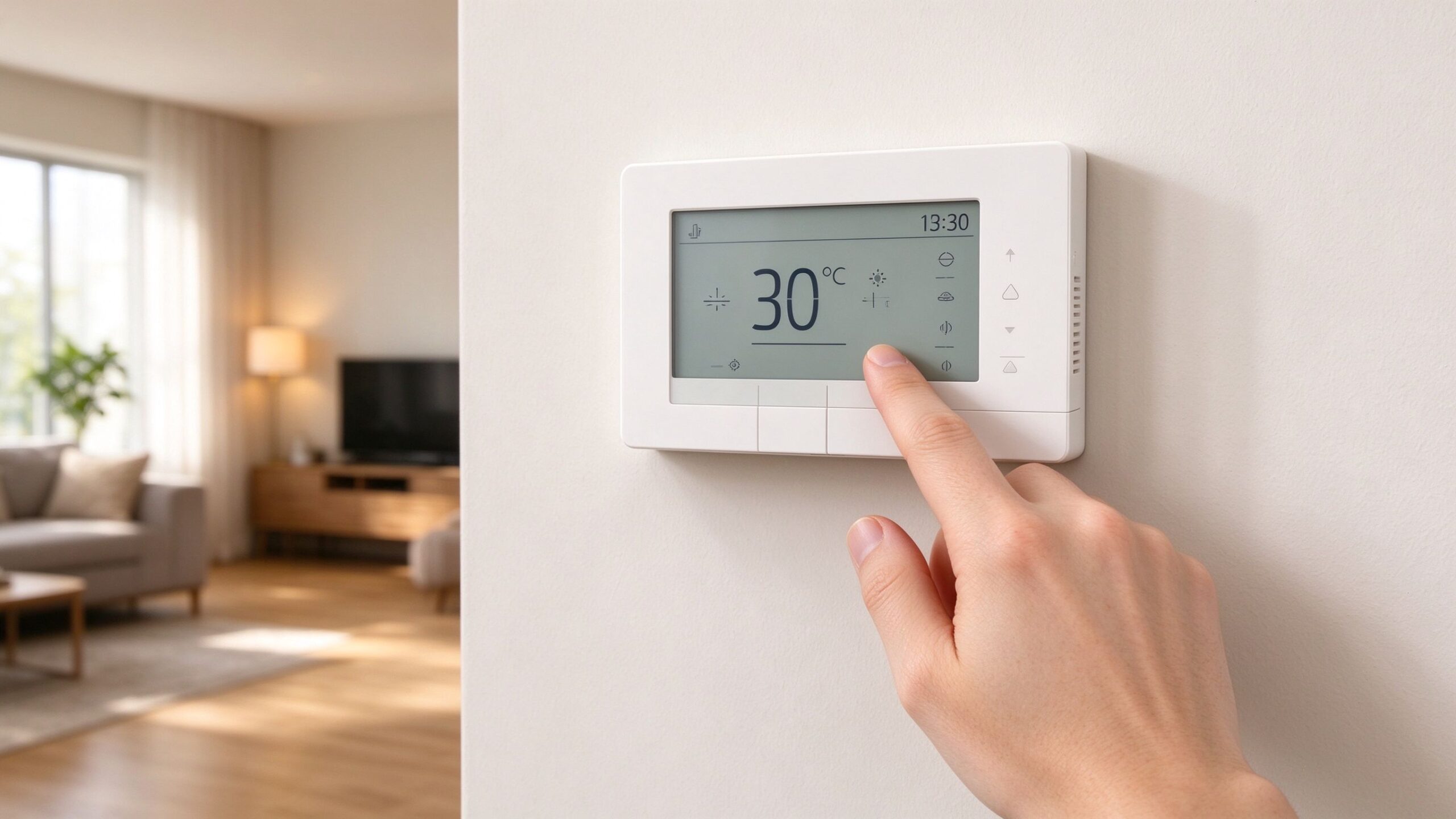
System types compared on how well they hold a setpoint
Not every system holds temperature the same way. The comparison below covers the electric options most buyers are offered, plus the hydronic alternative, on the parameters that decide whether a setpoint can actually be respected.
| Parameter | Heating film (floor or ceiling) | Heating mat (thin, under tile) | Heating cable (in screed) | Hydronic UFH |
|---|---|---|---|---|
| Typical power density | 80–160 W/m² | 120–200 W/m² | 100–150 W/m² | Design output typically 60–100 W/m² |
| Voltage | 230 V AC, or 12/24 V DC for low-voltage variants | 230 V AC | 230 V AC, three-phase for large areas | Mains-powered circulator, low voltage controls |
| Response to setpoint change | Fast, minutes for thin assemblies | Fast, 20–40 minutes | Slow, 3–6 hours | Slow, hours |
| Surface temperature controllability | Good with floor probe and a limiter function | Good, mat is close to the surface | Good but sluggish; probe must be in the right layer | Excellent with mixing valve and weather compensation |
| Overshoot risk | Low with proportional control; higher with simple on/off | Moderate on small zones | Low | Low |
| Typical service life | 20–30 years for the element, less for connectors | 15–25 years | 20–30 years | 25–40 years for pipe, less for the heat source |
| Indicative installed cost | Medium | Low to medium | High, screed and curing included | Highest, plus heat source |
| Typical setpoint fit | Retrofit, timber and laminate rooms with a strict 27 °C cap | Bathrooms, kitchens, small tile zones | New build with thermal stability priority | Whole-house new build at low flow temperature |
| Main limitation | Requires an accurate floor probe position | Small zones can cycle and overshoot | Slow to react; hard to repair under screed | Capital cost, response time |
Read the table for fit rather than for rank. In a laminate living room where the cap is 27 °C and the client wants fast response, film or mat with a floor-probe limiter is the practical choice. In a new-build house with a heat pump, hydronic is the better long-term answer, and the setpoint question becomes a matter of flow temperature and mixing valve design rather than element wattage.
How to set a thermostat so the cap is actually respected
Four settings decide whether the limiter works in the field:
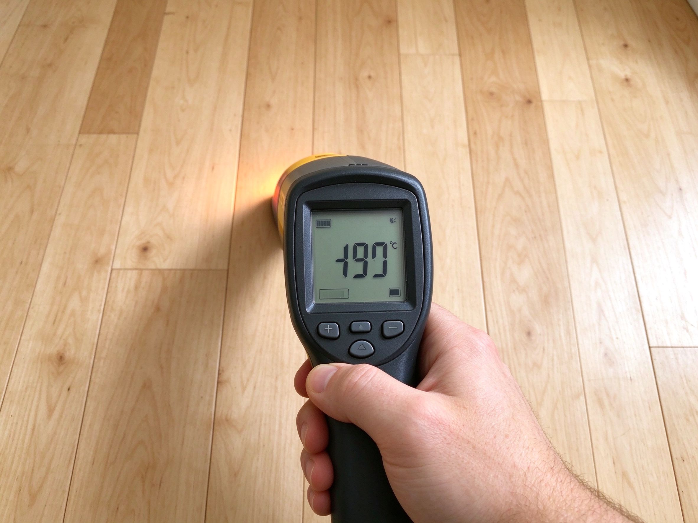
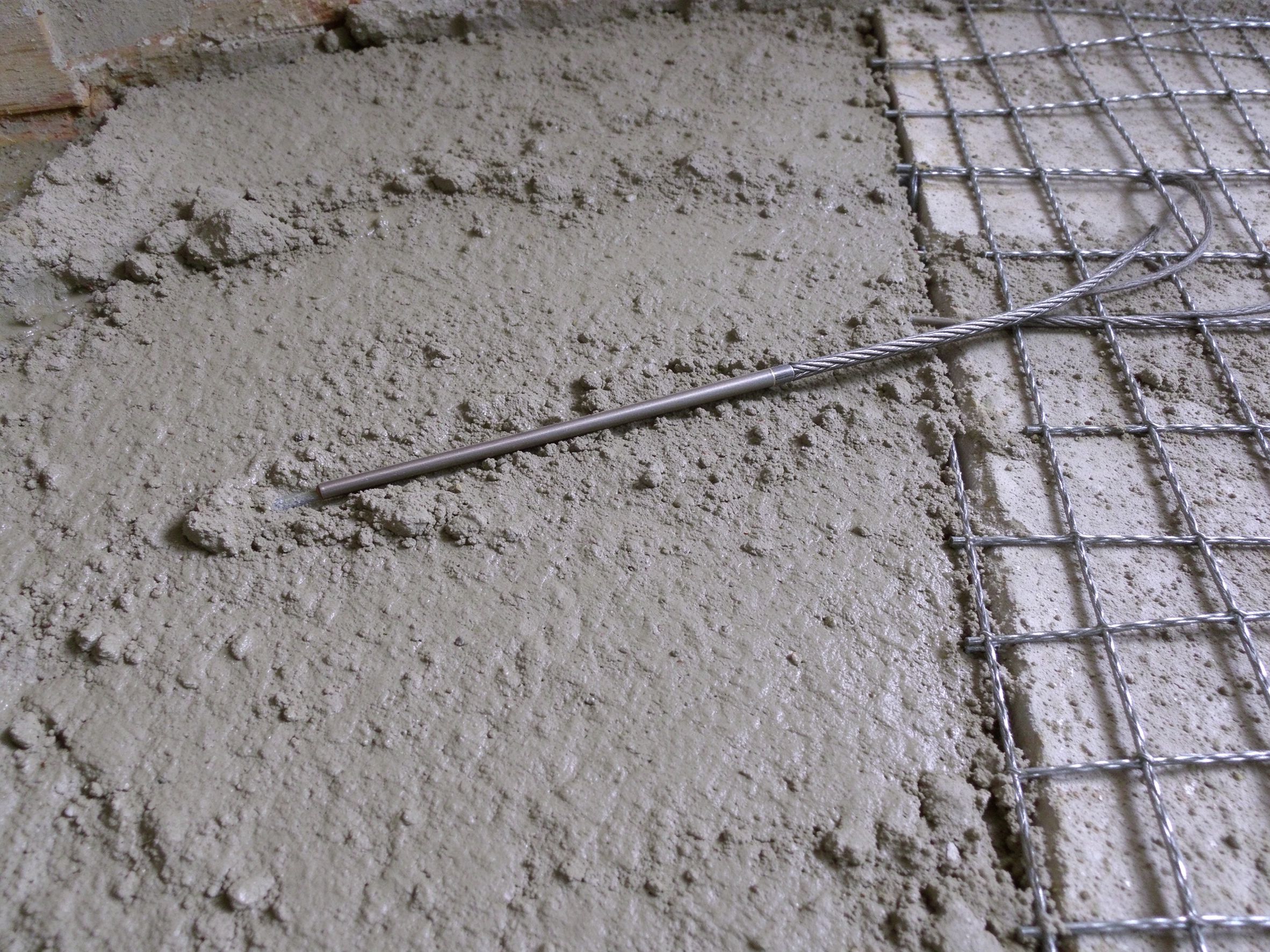
1. Probe position. The floor probe must sit in the layer whose temperature you are limiting, and the manufacturer’s installation depth must be followed. A probe buried too deep reads the slab, not the surface the covering sees, and will happily allow the surface to overshoot.
2. Dual-limit control. Use a thermostat that supports both an air setpoint and a floor limit, and set the floor limit 1–2 °C below the covering’s maximum. That margin absorbs sensor lag and probe tolerance.
3. Hysteresis and proportional control. A wide hysteresis band causes visible temperature swings; a proportional or PWM output holds a steadier surface. For small tile zones, PWM typically halves the swing compared with simple on/off.
4. Schedule and setback. A 2–3 °C night setback in bedrooms and living areas is reasonable where the floor is not heat-sensitive. A 5 °C setback in a timber room can cause more movement than the energy saved, because the floor heats and cools slowly and unevenly.
When to choose which setpoint strategy
Tile and stone rooms: control on air temperature with a floor cap at 29 °C, and allow a short drying excursion only if the assembly permits it. Fast-response mats or film suit these rooms.
Laminate and engineered wood: control on the floor cap at 27 °C as the primary limit, with air control as a secondary comfort layer. Check the board’s declared thermal resistance and its listing for underfloor heating before anything is installed.
Solid timber and some natural coverings: often not approved over underfloor heating. If a client insists, get written confirmation from the covering manufacturer and record it; otherwise choose a different covering or a different emitter.
Carpet: the limiting factor is the combined thermal resistance of carpet plus underlay, not the carpet alone. Choose a low-tog product and verify the total against the 0.15 m²K/W guidance.
Commercial and large open areas: zone by orientation and use, not by geography. A south-facing perimeter zone and an internal zone with the same setpoint will produce different floor temperatures at the same air temperature.
Procurement checklist before ordering a system with a temperature limit
- Floor covering type, product name and the manufacturer’s declared maximum surface temperature
- Declared thermal resistance (R-value) of the covering and any underlay, against the 0.15 m²K/W limit
- Whether the covering is explicitly listed as suitable for underfloor heating
- Thermostat specification: floor probe included, dual-limit capable, hysteresis or PWM output, load rating
- Probe type and cable length, installation depth and approved mounting method
- Zone count and the setpoint schedule the client expects, including night setback
- Screed type, curing record and moisture measurement before covering installation
- Commissioning requirement: surface temperature readings at three points per zone, recorded on handover
- Warranty terms for both the heating system and the floor covering, and which document governs the temperature limit
Seven setting mistakes that generate complaints
1. Setting a high floor temperature to speed up warm-up. The floor heats at the rate the assembly allows. Raising the cap does not shorten the wait; it only raises the peak.
2. No floor probe in a timber room. Air-only control over a heat-sensitive covering is the most common cause of gapping and cupping claims.
3. Probe in the wrong layer. A probe in the screed cannot see the surface. Follow the system manufacturer’s depth, not a rule of thumb.
4. Quoting the standard when the data sheet is stricter. 27 °C on the board beats 29 °C in the standard every time a warranty claim is made.
5. Ignoring the covering’s R-value. A thick underlay can push a perfectly good system past the resistance limit, and no thermostat setting will fix it.
6. One zone for a whole floor plate. Different rooms, coverings and orientations need different caps. A single zone forces the strictest cap onto every room.
7. Treating the setpoint as a comfort dial. Comfort comes from air temperature and even floor temperature together. Turning up the floor because the room feels cold usually means the room is under-insulated or the zone is undersized, not that the cap is too low.
Data and evidence
From SunAura factory records:
- 17 years of electric heating manufacture since 2008, Qingdao Huangdao plant
- ISO 9001, ISO 14001 and ISO 45001 certified management systems
- CE, RoHS, LVD and EMC documentation issued per production batch
- Export to 50+ countries, with thermostat ranges supporting floor-probe limiting and dual-setpoint control
From published third-party sources:
- EN 1264 series guidance for surface embedded heating, specifying a maximum floor surface temperature of 29 °C for living areas and a floor covering thermal resistance limit of 0.15 m²K/W
- National standard alignment, including ÖNORM B2242, which adopts the same 29 °C surface limit
- BEAMA and Contract Flooring Association guidance on underfloor heating, covering floor temperature interpretation and temperature compliance
- European Producers of Laminate Flooring technical bulletin on installation of laminate floor coverings, including limits for heated substrates
- Timber flooring manufacturer information sheets citing 29 °C per EN 1264 and a recommended indoor relative humidity range of 30–65 %
FAQ
What temperature should underfloor heating be set to? Air setpoint 20–22 °C in living areas and 22–24 °C in bathrooms, with a floor surface cap of 27 °C under timber or laminate and 29 °C under tile. The cap, not the air setpoint, is the hard limit.
Is 30 °C floor temperature too hot? For tile in a bathroom, briefly, it is tolerable if the assembly allows it. For laminate, engineered wood or carpet, it exceeds typical limits and puts the warranty at risk.
Why does my floor feel cold even though the thermostat reads 22 °C? Usually undersized output, missing insulation beneath the system, or a zone covering too large an area. Check the heat-loss calculation and the installed W/m² before blaming the setpoint.
Should I lower the setpoint at night? A 2–3 °C setback is reasonable in most rooms. In timber rooms keep the setback small, because slow, uneven cooling causes more dimensional movement than the energy saved.
Do I need a floor probe if I have a smart thermostat? Yes. A smart thermostat with no floor probe controls air only; the limiter still has to come from a sensor in the floor build-up.
Next step
If you are specifying a system and need to fix the caps before the covering goes down, send us the covering specification, its declared R-value and the room schedule. We will return a zone plan with setpoints, probe positions and a thermostat selection that actually enforces the limit. Useful background: how to calculate the right power density, expected service life for film, mat and cable, and electric versus hydronic systems compared. Thermostats with floor-probe limiting are listed on our K5 page and the wider heating film range.
Ethan Sun, Founder & CEO, SunAura Thermal