
Ethan Sun, Founder & CEO, SunAura Thermal
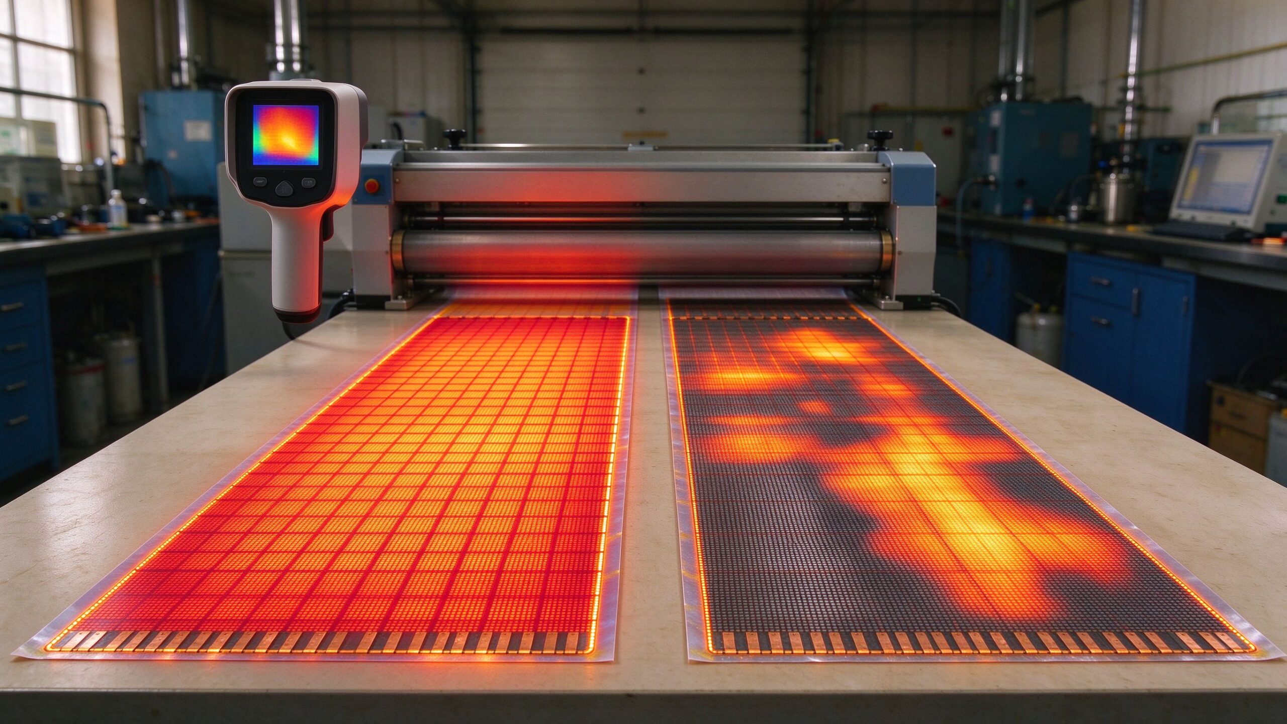
A heating film datasheet usually opens with power density and maximum surface temperature. The number that decides whether the film runs at the same temperature at the far end of a six-metre run as it does at the terminals is almost never printed: the bus bar. Buyers who compare films on W/m² alone are comparing the middle of the sheet and ignoring the edges, which is where most of the complaints come from.
We see this in the field regularly. An installer unrolls a 0.5 m × 6 m film, connects the cold lead, switches on, and the floor warms unevenly. The film is not defective. The current collection design cannot deliver the same voltage to both ends of the run, so the far end receives less power. On a 230 V film the loss is small enough that nobody notices. On a 24 V film with the same copper, it is large enough that the far half of the sheet barely warms at all.
This matters at the quotation stage, not the installation stage. If your specification says “160 W/m², 0.5 m wide, cut to length” and nothing about bus bar width, copper thickness or maximum run length, you have left the most consequential part of the design to whoever answers the enquiry. This article sets out what the bus bar does, how much copper different voltages demand, where the cut zone really ends, and what to put on the enquiry sheet so that two suppliers quote the same thing.
Why current collection decides uniformity, not the heating layer
An electric heating film is a distributed resistor. The active layer — carbon ink, graphene dispersion or a carbon-fibre mesh — has a resistance per square that sets the power density at a given voltage. The bus bar is a low-resistance strip running along one or both edges, whose only job is to carry current from the cold lead into the active layer along the full length of the sheet.
If the bus bar had zero resistance, every point of the active layer would see the same voltage and the sheet would heat evenly. It does not have zero resistance. Voltage falls along the strip as current flows through it, so the active layer near the far end sees a lower voltage than the layer near the terminals. Since power in a resistive element falls with the square of voltage, a 5 % voltage drop becomes a 10 % power drop, and a 10 % voltage drop becomes a 19 % power drop.
The arithmetic is simple enough to do on an enquiry sheet. For a copper strip, resistance is resistivity times length divided by cross-section. Take a 6 m length of 35 µm copper foil, 4 mm wide: the cross-section is 1.4 × 10⁻⁷ m², so the strip resistance is roughly 0.73 Ω. On a 230 V, 480 W film drawing 2.1 A, that is a 1.5 V drop along the whole run — about 0.7 %, which is negligible. Split the current between two edge strips and the drop halves again.
Now change the supply to 24 V. The same 480 W film draws 20 A. Through the same 0.73 Ω strip, the drop is 14.6 V — 61 % of the supply. The far end of the sheet sees under 10 V and produces a quarter of the design power. This is why low-voltage film is not simply “the same product at a safer voltage”. It is a different current-collection problem, and it is solved with thicker foil, shorter runs, more parallel strips, or all three.
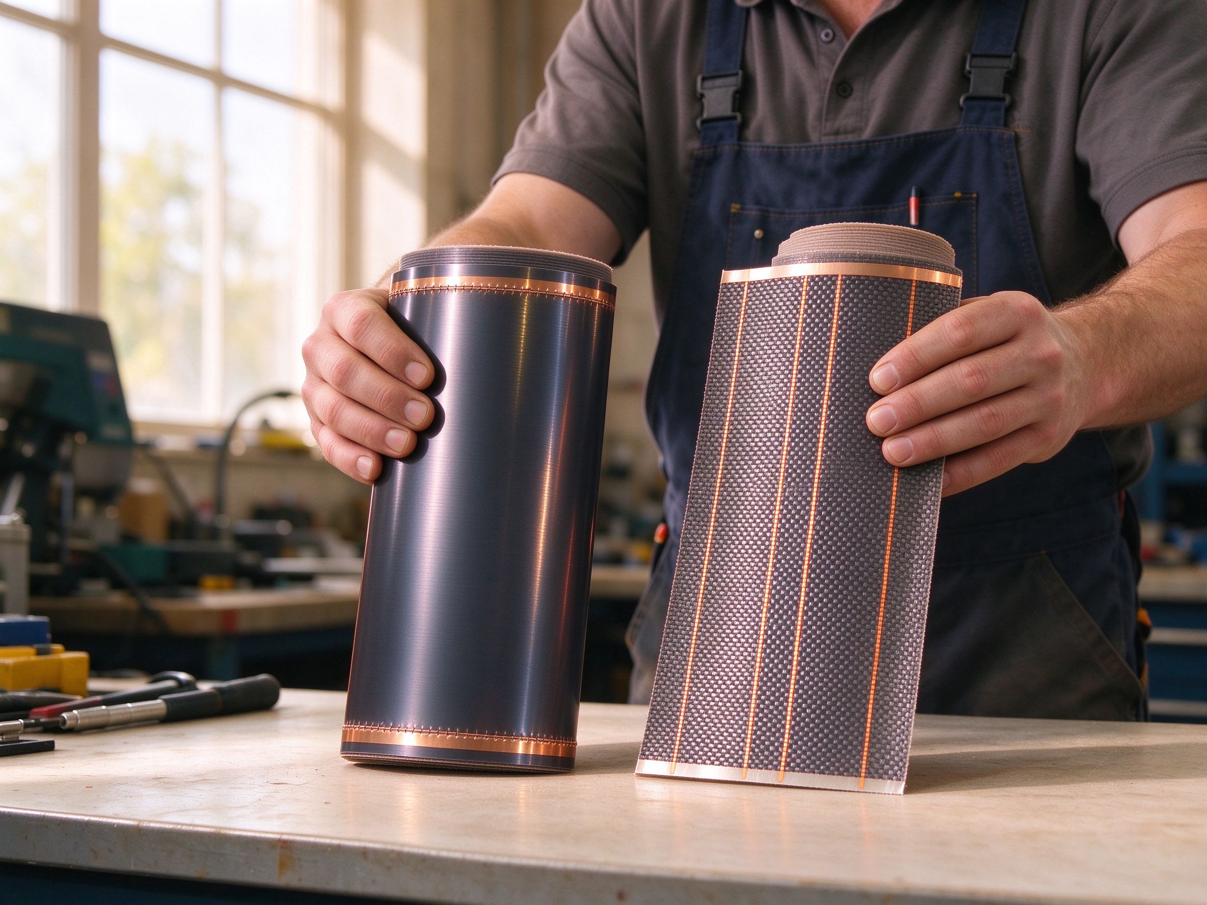
The practical consequence for buyers is that “160 W/m²” is not a complete specification. Two films with identical active layers and different bus bars will measure differently at the far end, and the difference grows with length. Ask for the end-to-end power deviation, not just the nominal density.
Bus bar materials compared: copper foil, printed silver, aluminium, braid
Four constructions dominate the market, and each is the right answer in a different product tier. The comparison below is the one we use internally when a buyer asks why one quotation is 30 % cheaper than another for what looks like the same sheet.
| Bus bar type | Typical construction | Resistance | Best suited to | Limit to watch | Cost position |
|---|---|---|---|---|---|
| Copper foil, laminated | 35–70 µm foil, 4–12 mm wide, heat-bonded to the active layer | Lowest of the four | 230 V floor and wall film, 4–8 m runs, low-voltage film in short lengths | Foil must not be creased during rolling; creases become hot spots | Reference cost |
| Printed silver electrode | Silver-filled ink screen-printed along the edge, 15–40 µm cured | Higher than copper, higher than aluminium | Thin, narrow film where a metal strip would add stiffness | Silver ink is the most expensive material per gram in the whole film | +10 to +25 % on electrode cost |
| Aluminium foil strip | 20–50 µm foil, 6–15 mm wide | About 1.6× copper for the same section | Short runs, low power densities, cost-sensitive mat products | Galvanic corrosion at the copper cold-lead joint if not sealed | −15 to −25 % on electrode cost |
| Tinned copper braid | Flat braid 3–8 mm, soldered or riveted | Low, and tolerant of flexing | Flexible film, curves, repeated handling, industrial wraps | Bulk and thickness; harder to laminate flat under a floor | +20 to +40 % on electrode cost |
Three things follow from that table. First, the electrode is a small share of the bill of materials but a large share of the failure modes — a film that is 8 % cheaper because it uses a narrower aluminium strip may cost the buyer far more in callbacks. Second, printed silver is not automatically the premium option: it is the right choice for very thin film where a metal strip would stiffen the product, and a poor choice for long 230 V runs where its resistance adds to the drop. Third, braid exists for movement, not for power density; specifying it on a flat floor film buys flexibility nobody needs.
What the cut zone actually means
Almost every heating film is sold as “cuttable to length”. Very few buyers are told what cutting does to the electrical result. The active layer of a film is a resistor across the bus bars. Shorten the film and you shorten the resistor, which lowers its resistance, which raises the power at a fixed voltage. A 6 m run cut to 4.8 m — a 20 % reduction — loses 20 % of its resistance and gains 25 % of its power. The remaining sheet now runs at 200 W/m² where the datasheet said 160 W/m².
That is not a defect of the product; it is what the physics does. It becomes a problem when a buyer cuts a film to fit a room and then specifies a thermostat and a floor build-up that were sized for the original density. The failure modes that follow are predictable: surface temperature above the limit of the floor covering, adhesive failure under vinyl, and a thermostat that cycles on its internal protection.
The cut line itself is also a manufacturing instruction, not a suggestion. Films are built with a defined cut zone between the bus bar and the active layer, usually 10–20 mm in from the edge. Cutting inside that zone damages the current path and creates a high-resistance sliver at the edge, which is exactly where a hot spot forms. Cutting across the bus bar severs the supply to the section beyond it, and the film downstream goes dead while still reading continuity at the terminals.
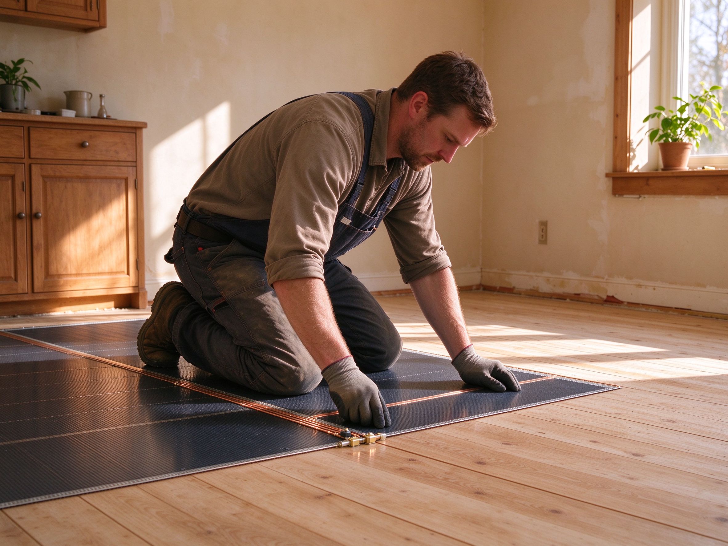
What to ask: the minimum and maximum cut length, whether the film can be cut from both ends or only one, and whether the power density after the shortest permitted cut still matches the floor covering. A supplier who cannot answer the third question has not thought about installation.
Where joints fail, and how to specify them
In our warranty records the film itself is rarely the failed component. The joint between the cold lead and the bus bar is. That joint carries the full circuit current through a connection that was made after the film left the factory, often in a floor, often by hand.
Three joint methods are in common use. Soldered joints give the lowest contact resistance but require the installer to control temperature on a 35 µm foil without melting the PET carrier underneath. Riveted or crimped joints are faster and more repeatable, but depend on the mechanical pressure staying constant through thermal cycling; a crimp that reads 2 mΩ at commissioning can read 40 mΩ after two winters. Conductive adhesive joints are the easiest to apply and the least stable, because the adhesive carrier creeps under load and the contact area slowly shrinks.
Whichever method is specified, three numbers decide whether the joint survives. Contact resistance at commissioning should be a few milliohms, not tens. The joint must be encapsulated against moisture — a floor is a wet environment over ten years, whatever the room above it looks like. And the joint must be testable after installation, which means it has to sit in an accessible position or be documented well enough that a later installer can find it.
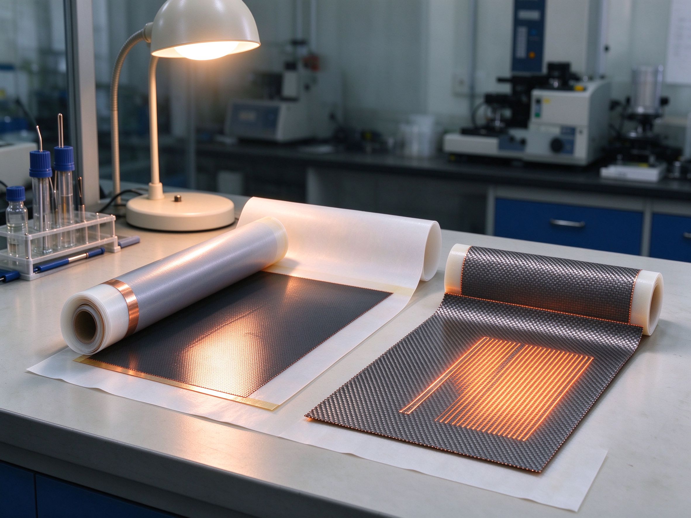
For buyers importing film, the joint question belongs in the purchase specification, not in the installation guide. If the film ships with factory-sealed cold leads, the buyer inherits a controlled joint and gives up the ability to shorten the sheet. If it ships as bare film, the buyer takes on joint quality and should expect the supplier to supply a matching joint kit, a torque or crimp specification, and a test procedure.
Selection framework by project type
The table above compares materials. This one compares applications, because the same film that is correct for a living room is wrong for a marine cabin and wrong again for a heated bench.
| Application | Power density | Supply | Practical run length | Bus bar priority |
|---|---|---|---|---|
| Residential floor, 230 V | 140–160 W/m² | 230 V AC | 4–8 m per strip | 4–6 mm copper foil; end-to-end deviation under 5 % |
| Commercial floor, 230 V | 160–220 W/m² | 230 V AC | 3–6 m, zoned | 6–10 mm foil; parallel strips on wide sheets |
| Wall or ceiling panel | 120–180 W/m² | 230 V AC | 2–4 m | Narrow foil or printed silver; low stiffness matters |
| RV, marine, off-grid | 80–150 W/m² | 12–24 V DC | 1–2.5 m | 70 µm foil or braid; short runs are mandatory |
| Industrial freeze protection | 10–40 W/m² | 230 V AC or 24 V DC | 5–15 m | Foil plus braid reinforcement at flex points |
| Bench, vivarium, propagation | 60–120 W/m² | 24 V DC or 230 V AC | 0.5–2 m | Uniformity over length; silver or thin foil acceptable |
The 24 V rows are the ones that catch buyers out. A 24 V film at 150 W/m² and 0.6 m width draws 3.75 A per metre of length. At 2.5 m the run is drawing 9.4 A through a strip whose resistance was designed for a fraction of that. Suppliers who sell 24 V film in long rolls without publishing a maximum run length are selling a product that will under-perform at one end, and the buyer will discover it in the first cold week.
The enquiry sheet: eight parameters
If you want comparable quotations from three suppliers, the enquiry has to pin down the parts that are otherwise quietly varied. These eight items are the minimum we would send, and the minimum we would want to receive.
One: power density at the stated voltage, with the tolerance — ±5 % is a normal factory figure, ±10 % hides a lot. Two: active layer material and carrier substrate, since PET and polyimide behave very differently at the temperature limit. Three: bus bar material, width and foil thickness. Four: maximum and minimum cut length, and the power density at the minimum. Five: end-to-end power deviation at the maximum run length. Six: cold lead length, joint method and whether the joint is factory-sealed. Seven: insulation resistance and dielectric withstand values, with the test voltage. Eight: the temperature the film is permitted to reach under the specified floor covering.
Add the commercial items that decide total cost rather than unit cost: MOQ per width, lead time for a custom length, whether cut-length film is priced per square metre or per piece, and what the supplier does about a roll that measures outside tolerance.
Five specification mistakes we see repeatedly
Comparing films on W/m² only. The density describes the middle of the sheet. Two films at the same density can differ by 8 % end to end, which is the difference between an even floor and a complaint.
Treating “cuttable” as “any length”. Cutting raises power density. A film cut 20 % shorter runs 25 % hotter at the same voltage, which is how a 160 W/m² product ends up above the 27 °C limit under engineered wood.
Specifying a 24 V film by the metre. Low voltage multiplies current. Run length has to be specified by the supplier, not estimated by the buyer from the roll size.
Buying aluminium because it is cheaper. Aluminium is a legitimate choice for short, low-density runs. It is a poor choice where the cold lead is copper and the joint sits in a damp floor, because the galvanic couple corrodes exactly at the point nobody can reach later.
Leaving the joint to the installer without a procedure. The joint is the highest-risk connection in the whole system. If the film ships bare, the purchase order should carry a joint method, a contact-resistance limit, and a requirement that the joint be encapsulated and recorded.
Data and evidence
The numbers in this article come from three places: standard resistive-load arithmetic that any buyer can repeat, our own factory measurements, and the installation records behind our warranty returns.
Factory side: SunAura Thermal has manufactured heating film, mat, cable and controls since 2008 — seventeen years of production from the Qingdao (Huangdao) plant, operating under ISO 9001, ISO 14001 and ISO 45001, with CE, RoHS, LVD and EMC documentation for the product lines and distribution into more than 50 export markets. We do not publish certificate numbers in marketing copy; buyers receive current documentation with the quotation.
Test side: every film batch is checked for surface power deviation across the sheet, and the end-to-end deviation at maximum run length is recorded rather than inferred. Insulation resistance and dielectric withstand are tested at the film level before lamination into mats. Thermal imaging is used on sample runs to find hot spots at cut edges and joints, because those are the two locations where a film fails in service.
Field side: the warranty return pattern is consistent enough to be useful. Joint failures outnumber active-layer failures by a wide margin, and cut-edge hot spots cluster in installations where the film was trimmed inside the marked zone. Neither pattern is visible on a datasheet, which is why both belong in the purchase specification.
FAQ
Does a wider bus bar always mean a better film? Up to a point. Going from 4 mm to 8 mm copper roughly halves the strip resistance and cuts the end-to-end drop accordingly. Beyond the point where the drop is under about 3 %, extra copper adds cost and stiffness without changing what the floor feels like.
Can I use the same film at 12 V and 230 V? No. Power scales with the square of voltage, so a 230 V film run at 12 V produces about 0.3 % of its rated output. Low-voltage products are separately designed around high current and short runs.
Why does the end of my film run cooler than the start? Voltage drop along the bus bar. It is normal to a degree and specified as end-to-end deviation. If the difference is visible to the hand, the run is too long for the bus bar section or the supply is too low for the length.
Is a printed silver electrode worth the premium? For thin, narrow film where a metal strip would stiffen the product, yes. For long 230 V floor runs, copper foil usually wins on both resistance and cost per metre of current carried.
What tolerance should I accept on power density? ±5 % is a realistic factory band for film. Wider bands are not automatically bad, but they shift the responsibility for thermostat and floor-covering compatibility onto the buyer, because the installed density may sit outside the design figure.
Next step
If you are sourcing film for a project, send the room schedule with length, width, voltage and floor covering rather than a single power density. We will return a film specification with the bus bar section, the maximum run length at your voltage, and the density you get after the shortest permitted cut — the three numbers that decide whether the finished floor heats evenly. The heating film product range lists the standard widths and densities; our comparison of PET and polyimide carriers explains the temperature side, and the wattage calculation guide covers how density is chosen in the first place. If you are weighing film against cable for the same room, the film versus cable comparison sets out where each one wins.