
Factory-built modules change where the heating decisions are made
A building that arrives on site as a series of finished modules does not tolerate a traditional heating schedule. On a conventional build, the floor goes down, then the heating contractor arrives, unrolls cable or mat, and works around everyone else. In a modular factory, the floor is assembled on a bench, on a production line, on a Tuesday, and the module is bolted together on a Saturday three weeks later. If the heating is not designed into that sequence, there is no later window to install it — the floor is sealed before the module ever leaves the yard. This article explains how prefab underfloor heating is actually integrated, where the risks sit, and what a developer or module maker should specify before the first panel is cut.
The headline opportunity is real. Thin electric heating mats and heating film add almost no build-up height, carry no water, and can be pre-wired with connectors the same way plumbing and lighting already are in a module factory. That makes them a natural fit for off-site construction in a way hydronic pipe, with its manifolds and pressure testing, rarely is. The catch is coordination: every advantage depends on design decisions made months earlier, and the module line exposes any missing detail far faster than a building site does.
Anna Kowalski, Industry Analyst, SunAura Thermal
Two integration routes: factory fit and site fit
There are exactly two ways to put heating into a modular project, and the choice should be made at the project’s design stage rather than discovered during fit-out.
Factory fit. The heating element is laid into the floor cassette while the module is on the production line — the mat or film goes onto the deck, the cold leads are routed to a service point, the floor finish is applied over the top, and the electrical connections are tested before the module is wrapped for transport. The building arrives on site with the heating already inside it. This is the route that captures the real productivity gains: installation time moves from a wet, crowded site to a dry bench where work is repeatable and can be quality-controlled at every station.
Site fit. The modules are designed with a reserved floor build-up and a service void, but the heating is installed after the modules are craned in and joined — typically an ultra-thin mat under a late floor finish, or heating film in a dry-lay system. This route suits projects where module designs vary a lot or where the heating specification is decided late, such as a rental portfolio where different tenants want different finishes. It gives up most of the factory productivity advantage but keeps flexibility.
The hybrid that causes trouble is the third, unplanned route: modules designed with no heating provision at all, into which a developer tries to retrofit heat after handover. A sealed factory floor with no reserved build-up leaves roughly the same options as any retrofit — surface-mounted mats, raised floors, or tearing out finishes — and the cost lands after the project budget has closed. The single most useful question a modular developer can ask at the first design meeting is simply: which of the two planned routes is this project using?

Why thin electric systems dominate the modular floor
The physical constraints of a module explain the product choice without much argument. A floor cassette has a fixed, tightly engineered build-up; every millimetre added to the floor changes door heights, threshold details and how modules stack for transport. A 3–4 mm heating mat, or a sub-millimetre heating film under a dry board, fits inside a build-up that a screeded hydronic system simply cannot. There is no wet trade, no drying time, and the line never waits for a compound to cure.
Weight is the second argument. Modules are lifted by crane and transported by road, and every kilogram in the floor is a kilogram paid twice — in transport and in the structural design of the cassette. A thin mat weighs a few hundred grams per square metre; a filled screed adds tens of kilograms. For multi-storey modular stacks, where the lower modules carry everything above them, that difference compounds floor by floor.
The third reason is electrical rather than structural. A module is already a pre-wired unit: lighting, sockets, ventilation and controls are installed on the line and tested at a dedicated station. Heating joins the same workflow naturally — cold leads terminate at a fixed service point, a multi-pin connector plugs into the module’s electrical harness, and the test is a checkbox beside the rest of the electrical sign-off. A smart thermostat can be mounted and paired in the factory, so the end user gets a finished, commissioned system rather than a pile of loose components.
| Factor | Thin electric mat / film | Hydronic pipe in screed |
|---|---|---|
| Added floor build-up | 3–4 mm mat; film under dry board | Often 50–70 mm with screed |
| Weight added per m² | Under 1 kg | 50 kg+ with wet screed |
| Wet trades on the line | None | Screed, pressure test, drying wait |
| Factory testing | Electrical continuity at a station | Pressure test, leak risk in transit |
| Module-to-module join | Plug connectors, no fluids | Manifolds and couplings on site |
The connector and load detail that decides whether modules plug together
On a building site, an electrician can route cable however the room demands. On a module line, every connection has to be identical, because the module next week may be assembled by a different team and joined to a module built in a different factory. Standardisation is therefore the engineering heart of a prefab heating system.
Three decisions do most of the work. First, a fixed service point: every module terminates its heating cold leads at the same physical position, with the same connector type and pin assignment, so joining two modules on site is a plug operation rather than a wiring exercise. Second, documented load per module: the total wattage of the floor is written on the module’s electrical schedule so the site team and the distribution board designer know exactly what each module draws — a 40 m² module at 150 W/m² is a 6 kW load, and that number has to exist before the panel is sized. Third, a clear split between what is tested in the factory and what is connected on site, so responsibility for a fault is never ambiguous.
Voltage deserves a conversation of its own. A module fleet destined for one country can be built around a single supply standard, but export projects often cross voltage regimes. Where a line feeds multiple markets, the heating design should keep the low-voltage element and the supply-side switching separate, with the thermostat and any contactor specified per destination rather than baked into the cassette. The floor element can then be common across the whole fleet while the control pack changes by market, which is far simpler than maintaining two floor designs.
What the factory test station has to catch
A module is sealed before it travels, which means a heating fault found after installation is not a repair — it is a finished-floor problem. The factory test station is therefore where the system’s reliability is actually decided, and it should run the same checks a good heating factory uses on every roll.
Three checks belong in the line sequence. Continuity confirms the element is intact after the floor board has been laid on top of it, catching a nail or screw driven through the mat during assembly. Insulation resistance confirms no conductor is close enough to the structure to leak current, the same measurement that would be made on a conventional install. And a functional check energises the system briefly through its actual connector and thermostat, proving the whole chain — element, cold lead, plug, control — rather than testing components in isolation. Each result belongs on the module’s electrical certificate, because the developer’s handover pack is the only record the site team will have.
Transport is the next hazard. A module that passes every bench test can still be damaged on a truck: vibration, flexing as the unit is lifted, and cold temperatures if it is moved in winter. The routing of cold leads matters here — they should be clipped, not left free to chafe, and the connector should have a protective cap for the journey. A repeatable loading checklist is dull, but every module maker who has debugged a fault 300 kilometres from the factory has eventually written one.
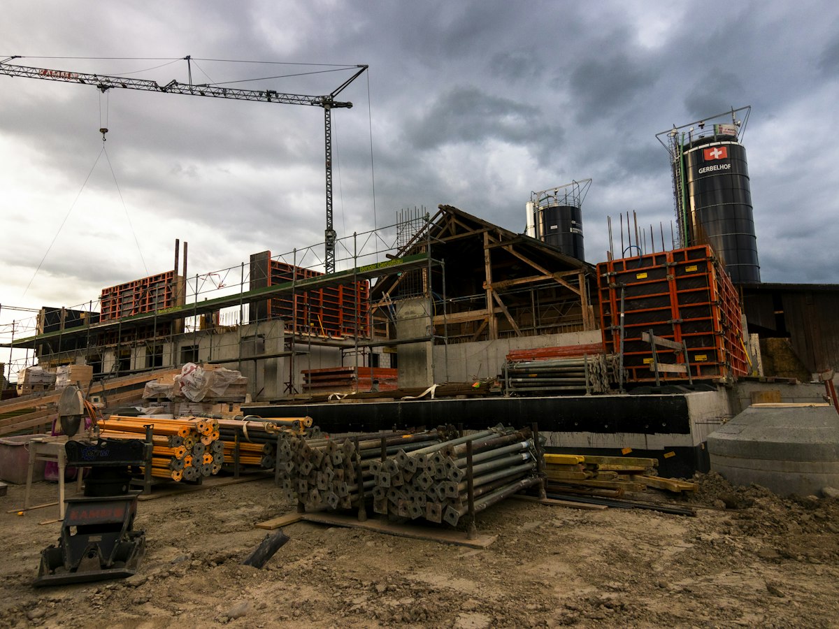
Coordinating the floor across the module boundary
Modules are warm, comfortable rooms until you stand at the join between them. The floor finish, the skirting and the heating all have to cross a gap that moves slightly as the building settles, and heating design has a specific job at that boundary.
Elements should never be laid across a module join. A mat or film that spans two modules is flexed every time the units are lifted separately and again as the building moves, and the conductor cannot survive that. Instead, each module carries its own element up to a defined edge, and the two zones meet at the join with a small unheated gap covered by the floor finish. The thermostat zones are then planned to match the module layout rather than fight it: a living-zone module and a bedroom module are natural separate zones, each with its own control, which also suits the way occupants actually use the building.
For larger open-plan spaces assembled from several modules, the coordination job is the heat pattern. A row of modules each heated to the same density can leave a faint band at every join if the layout is not planned, so the design should specify element spacing that continues visually across the boundary — same edge distance, same wattage — even though the physical elements remain separate. It is a small drawing detail, but it is the difference between a floor that feels continuous and one that reads as a series of boxes.
How buyers and developers should approach the specification
The procurement pattern for a modular project differs from a conventional heating order, and a few questions asked early prevent expensive rework. The module maker should be able to answer all of them from the production documentation rather than from a sales conversation.
- Build-up and floor finish: exactly where the element sits in the cassette, and which finishes — tile, vinyl, engineered wood, carpet — are approved over it.
- Wattage per module and total load: the number on the electrical schedule, matched to the distribution design and any contactor.
- Connector standard: the exact connector, pin assignment and service-point position, identical across the fleet.
- Test evidence: continuity, insulation resistance and functional checks recorded per module, with the certificate in the handover pack.
- Repair strategy: what happens if a module fails after sealing — access panels, spare zones, rated repair kits — agreed before the first unit ships.
- Spare parts and repeatability: whether the same element and connector will be available for a second phase a year later, so extensions match the original fleet.
For developers sourcing across multiple projects, there is also a fleet argument. A standardised heating specification — one element family, one connector, one test protocol — lets different module factories build interchangeable units and lets the developer’s maintenance team carry one set of spares. The savings from that standardisation are larger than any unit-price difference between heating suppliers.
Data and evidence
The physical figures in this article — 3–4 mm mat build-up, sub-millimetre film, load calculations such as 6 kW for a 40 m² module at 150 W/m² — follow the way thin electric systems are specified for factory floors and can be checked against any product datasheet. The build-up and weight comparison with screeded hydronic systems reflects standard construction practice rather than a single laboratory test, and exact values should be confirmed against the module’s structural design.
The production and testing descriptions reflect SunAura factory records: heating mats and film supplied for module integration, with continuity, insulation resistance and functional checks run at the point of manufacture, and connector and service-point details documented per project. Certification and factory facts follow the same records: manufacturing in Qingdao, Huangdao District since 2008, ISO 9001, ISO 14001 and ISO 45001 management systems, CE and RoHS marked products, LVD and EMC tested, exported to more than 50 countries.
As with all our guidance, certificate numbers are not printed in articles because the documents change with each audit cycle; current Declarations of Conformity and test reports are supplied with quotations, and a module maker should be able to tie each delivered batch to the documents behind it.
FAQ
Can underfloor heating be added after the modules are installed? Only if the modules were designed with a reserved build-up or service void. A fully sealed factory floor leaves the same costly retrofit options as any finished building, so the heating route should be decided at the design stage.
Why not use water-based pipe in modules? It is possible, but the screed adds build-up and weight, needs wet trades and pressure testing on the line, and any leak in transit is destructive. Thin electric systems avoid all three and match the way modules are already pre-wired.
What happens to the heating at the join between two modules? Each module carries its own element up to a defined edge; nothing spans the join. Zones are planned around the module layout, and the finish covers the small unheated gap.
How is a fault found before the module leaves the factory? Continuity, insulation resistance and a functional energising test through the actual connector, all recorded on the module’s electrical certificate. A sealed module with a fault is caught at the test station rather than on site.
Can the same floor design serve different export markets? The heating element can be common across markets; the thermostat and any contactor are specified per destination because voltage and wiring rules differ. Keeping the two parts separate is the simplest way to run one fleet across several countries.
Next step
Send us the module floor build-up, the planned finish, the target market and the production volume. We will return the element specification, the connector and service-point detail, the per-module test protocol and a quotation, usually within one working day. If you are comparing suppliers, ask each one how the heating is tested at the line and how a sealed module is repaired — the answers tell you far more than the price per square metre.
Anna Kowalski, Industry Analyst, SunAura Thermal