
Introduction: Why Heat Tracing Is an Engineered Discipline
The easiest way to under-specify a heat-trace system is to treat it as a length of heater taped to a pipe. In a domestic setting that casual approach may hold a water line above freezing through a short cold spell. In an industrial plant, where the same cable may be responsible for a process fluid across a long, insulated, and largely inaccessible pipe run, the consequences of that mindset are more serious: a single under-sized or unmonitored circuit can stop a transfer, solidify a line, or rupture a pipe when its contents freeze and expand. The reason heat tracing is treated as an engineering discipline rather than a fitting is that its failure is usually discovered at the worst possible moment and the affected components are the hardest to reach.
This guide therefore works through the full sequence rather than starting with a catalogue. The objective has to be named first, because freeze protection and process maintenance lead to different calculations; the cable is then selected from a heat-loss figure rather than a nominal wattage; the circuits are laid out around the plant and the vulnerable components; controls and monitoring are specified; and the system is commissioned, documented, and maintained. Each stage depends on the one before it, which is why the order matters as much as the individual choices.
The Two Purposes of Heat Tracing
Industrial heat tracing is the discipline of applying controlled electric heat to pipes, vessels, and equipment to keep fluids at the temperature a process requires. It is easy to confuse it with simple domestic freeze protection, but the two differ in scope, precision, and accountability. A freeze-protection cable only has to keep water liquid; an industrial heat-trace system may have to hold a viscous process fluid at a defined temperature across hundreds of metres of pipe, through years of cycling, and within a documented safety regime.
Freeze protection maintains pipe contents above freezing during ambient low-temperature events; the target is a minimum temperature and the system often energises only in cold conditions, common on water, wastewater, and fire-protection lines in unheated spaces. Process temperature maintenance holds a fluid at the temperature needed for it to flow, react, or store correctly; the target may be well above ambient and is set by the material’s viscosity and handling requirements. Some systems combine both, protecting against freezing in idle periods and maintaining process temperature during operation, and the design must account for both regimes rather than optimising for one.
Cable Types and Where Each Is Used
No single cable suits every application. Self-regulating cable adjusts its output along the length in response to temperature, producing more heat where cold and less where warm, and it cannot overheat from its own output under the specified conditions; it can usually be cut to length on site and is widely used for both freeze protection and process maintenance. Constant-wattage cable delivers a defined, steady output and is used where a predictable heat input is required across a range of temperatures, often for longer runs and higher maintenance temperatures.
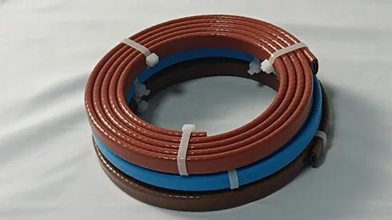
Silicone-rubber cable uses a flexible, high-temperature jacket and tolerates demanding environments and a wide temperature range, including low-temperature flexibility useful on exposed and repeatedly cycled equipment; the silicone versus PVC jacket comparison sets out the selection criteria. Mineral-insulated and specialty constructions are reserved for high-temperature or mechanically severe service. The choice accounts for the maintenance temperature, the maximum exposure temperature — including any steam-cleaning or process upset conditions — the chemical environment, and mechanical abuse. A cable rated for normal operation but not for an occasional high-temperature cleaning cycle is a common specification failure.

Design Inputs and Heat-Loss Calculation
A defensible design begins with data, not cable. The engineer needs the pipe or vessel dimensions and material; the fluid and its properties, including viscosity and the minimum handling temperature; the required maintenance temperature and any limits; the lowest expected ambient temperature and whether the location is exposed, sheltered, or indoors; the thermal insulation type and thickness with cladding or vapour barrier; and any process conditions that raise surface temperature. These inputs determine the heat the cable must supply, the dominant variable being heat loss through the insulation.
The core calculation establishes the heat loss per unit length at the maintenance temperature, then confirms the selected cable’s output at that temperature exceeds the loss with an appropriate margin. This distinction matters because cable output is temperature-dependent, especially for self-regulating products: a cable’s nominal output at one temperature is not its output at the maintenance temperature, and the selection uses the output curve at the actual operating point. A margin covers variation in insulation, installation quality, and uncertainty. Under-sizing produces a system that holds temperature in mild conditions but cannot recover after a cold spell; over-sizing adds cost and complicates control. Vessels and tanks are treated separately with a surface heat-loss calculation, and the cable or heating blanket is laid out to cover the area evenly.
Worked Heat-Loss Logic and Vessel Considerations
The calculation is best understood through its logic even where the exact figures are project-specific. For a given pipe at a maintenance temperature, the engineer reads the heat loss per metre from the insulation build — determined by the pipe diameter, the insulation thickness and conductivity, and the difference between the maintenance temperature and the design ambient. The selected cable’s output is then read from its curve at that same maintenance temperature, and the design is accepted only where the output exceeds the loss with a margin. If the cable output falls short, the remedy is not to assume a higher nominal wattage but to move to a different cable class, thicker insulation, or a split circuit, because a nominal figure measured at a different temperature does not represent the operating point.
Vessels and tanks break the linear assumption and are treated separately. A tank presents a large surface rather than a run, so the heat loss is calculated over the area and the heating element — whether cable arranged in a pattern or a purpose-built heating blanket — is distributed to cover it evenly, with attention to the base, fittings, and any areas where fluid can settle. The same traceability and control logic apply, but the layout is two-dimensional rather than a straight length. This is why a pipe cable and a tank heater are not interchangeable even when their nominal wattage looks similar.
Circuit Layout
Once the cable type and length are established, the system is divided into electrical circuits. Circuit length is bounded by the cable’s maximum run, the voltage drop over the length, and the current the protection and supply can carry. Long pipe racks are split into multiple circuits, each identified and routed so it can be controlled and isolated independently, grouped by area or service with junction points positioned where they remain accessible and protected. A good layout also protects the vulnerable components: valves, flanges, pumps, and instrument connections have greater exposed surface and require extra cable length, and the design allocates specific allowances rather than running a straight length and leaving fittings cold. Support points and pipe shoes, which conduct heat away, are handled in the same way. Cold leads and terminations are the most failure-prone elements, so their routing, strain relief, and sealing are specified rather than left to the installer’s discretion.
Electrical Design, Controls, and Monitoring
The electrical design provides overcurrent protection, earth-leakage protection appropriate to the cable and environment, and a clearly labelled distribution arrangement that maps each circuit to its pipe section. Controls fall into two broad approaches: ambient or line-sensing thermostats energise circuits based on temperature, common for freeze protection, while process control uses pipe-mounted sensors that read the actual maintained temperature, often with local indication and high- or low-temperature alarms. Where a single panel manages many circuits, centralised monitoring makes faults and operating states visible. Mechanical switching of large loads is handled through contactors rated for the current, with the control device switching the contactor rather than carrying the load directly. For safety-critical or high-temperature service, the design may include redundancy and fault indication so a failed circuit is detected before it compromises the process.
Installation, Commissioning, and Testing
Heat-trace installation is disciplined work because the cable is inaccessible once insulation and cladding are fitted. The cable is secured at controlled intervals, routed to follow the pipe rather than stretched across gaps, and given the specified extra length at valves and fittings, kept clear of sharp edges, moving equipment, and high-temperature points beyond its rating. Terminations are made to the manufacturer’s procedures, with sealing appropriate to the environment. Insulation is installed only after the cable is in place and tested, and the vapour barrier or cladding is sealed so moisture cannot enter, since wet insulation loses effectiveness and can accelerate corrosion.
Commissioning is the verification gate before handover. It includes continuity and resistance checks on each circuit; insulation resistance testing to verify electrical integrity, often recorded before and after insulation is applied; functional testing of controls, sensors, contactors, and alarms; and documentation with circuit identification, test records, and as-built drawings. These records establish the baseline against which future maintenance is compared and allow faults to be located without dismantling insulated pipe blindly.
Maintenance Through Operating Life
A heat-trace system is a long-term asset and needs a defined maintenance program, particularly in plants that depend on it for process continuity. Routine maintenance re-tests insulation resistance, verifies control and alarm function, checks terminations and panels, and inspects insulation and cladding for damage that would increase heat loss. Any section opened for pipework repair is re-tested before it is re-covered. Because cable faults often present first as a change in insulation resistance or a loss of circuit indication, trending those readings over time gives early warning. A common failure mode is unrelated to the cable itself — damaged insulation, a tripped circuit, or a disconnected supply leaves a correctly installed system unprotected, and none of these is visible without inspection. Trending also reveals developing moisture ingress or terminations loosening under thermal cycling, turning maintenance from a compliance exercise into an early-warning system. The field case of a dairy farm protecting hundreds of metres of water line through a severe winter shows the same exposure, and the choice between the two principal cable families is set out in the self-regulating versus constant-wattage procurement comparison.
How Buyers Should Evaluate a Proposed System
For a procurement team comparing proposals, the quality of a heat-trace design can be tested with a short set of questions before price is even discussed. A credible proposal names the design objective and target temperatures, shows the heat-loss calculation and the cable output at the maintenance temperature rather than a nominal wattage, identifies how circuits are divided and which pipe section each serves, lists the vulnerable components and the extra cable allowed for them, and specifies the controls, monitoring, and electrical protection. A proposal that leads with a single cable model and a per-metre price, without those elements, is effectively asking the buyer to do the engineering after purchase.
The same logic applies to the documentation set. The as-built circuit drawings, test records, and traceability back to cable batches are what make the system maintainable over a period of years, and their absence is a cost that only becomes visible when a fault has to be located in insulated pipe. Treating complete documentation as a required deliverable, rather than a nice-to-have, is one of the simplest ways to separate a well-engineered proposal from a generic one.
Conclusion
Industrial heat tracing is an engineered system rather than a cable attached to a pipe. Its reliability is decided in sequence — accurate process inputs, a heat-loss-based selection, a disciplined circuit layout, monitored controls, verified commissioning, and a maintenance program that keeps the system performing across years of cycling. Specified and documented that way, it holds fluids at the temperatures a process depends on, protects vulnerable lines through winter, and converts a hidden utility into a system that can be monitored, verified, and trusted. The alternative — a nominal heater chosen without the calculation — is the kind of saving that tends to be repaid many times over when the first severe winter arrives.