
Ethan Sun, Founder & CEO, SunAura Thermal
A dead heating zone almost always announces itself in one of four ways: the breaker trips as soon as the thermostat calls for heat, the thermostat shows a fault or reads a floor temperature that never rises, one room stays cold while the rest of the floor works, or the resistance reading at the thermostat terminals is nowhere near what the installation record says it should be. Each of those points to a different failure, and each has a different repair path and a different cost.
The expensive mistake is not the fault itself. It is skipping the diagnosis and going straight to a decision, either “rip it out” or “it will be fine”, because both are guesses and both are expensive. This guide sets out the sequence that a competent engineer should follow, what each test can and cannot tell you, and the point at which repair stops being rational.
First, separate the three failure families
Failures in electric floor heating fall into three families, and the tests that identify them are different.
The first is an open circuit, where the element is broken and no current flows. Resistance reads infinity. The breaker does not trip. The thermostat may show a fault code or simply never reach setpoint.
The second is a short circuit or a low-resistance fault, where insulation has broken down and the element is connected to earth or to the screen. Insulation resistance collapses, the RCD or RCBO trips, and the zone cannot be energised at all.
The third is a partial fault, where the element still works but a section has lost output or the termination has developed resistance. Resistance reads high, the floor heats unevenly, and the zone draws less current than the design figure. This is the family that gets misdiagnosed as a thermostat problem, because the thermostat is doing exactly what it was told with a floor that is not responding as expected.
Before any of that, rule out the controls. A thermostat with a failed probe, a mis-set parameter or a blown internal fuse presents as a dead zone. Disconnect the element at the thermostat and measure the element alone. If the element reads correctly, the fault is in the control chain, and the rest of this guide does not apply.
The measurement sequence, in the order it should be done
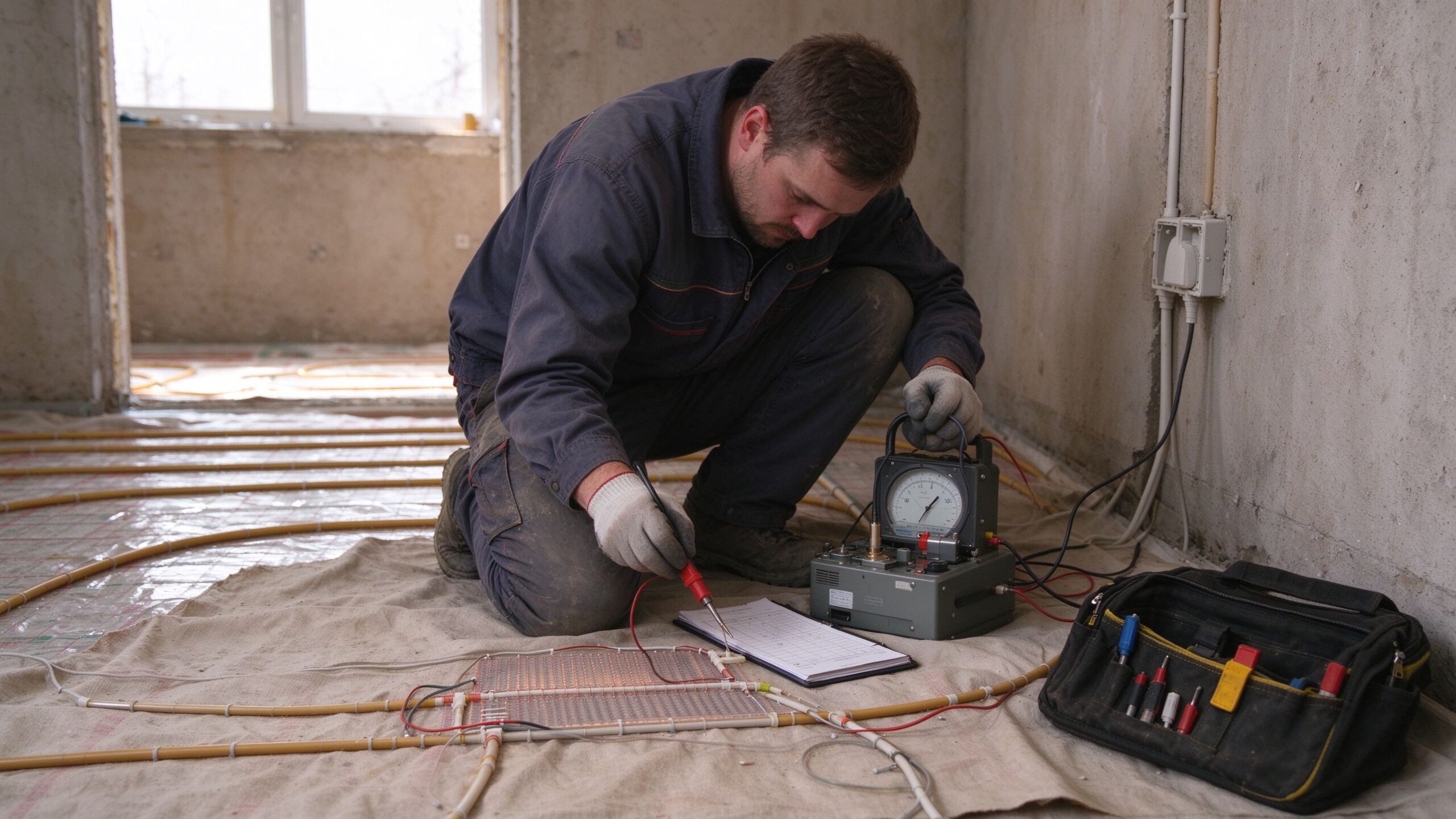
Isolate and prove dead. Lock off the circuit, prove the tester on a known live source, then prove the circuit dead. This is not a formality; electric floor heating faults are often investigated by people who are standing on a floor that may become live if a section is re-energised by a neighbouring circuit.
Measure insulation resistance at 500 V DC. Disconnect the element from the thermostat, join the two element conductors together, and measure between the joined conductors and earth. A healthy new installation reads in the hundreds of megohms. A reading below 1 MΩ indicates moisture ingress or insulation damage. A reading near zero means a hard earth fault. Test both live-to-earth and screen-to-earth if the cable is screened.
Measure conductor resistance.
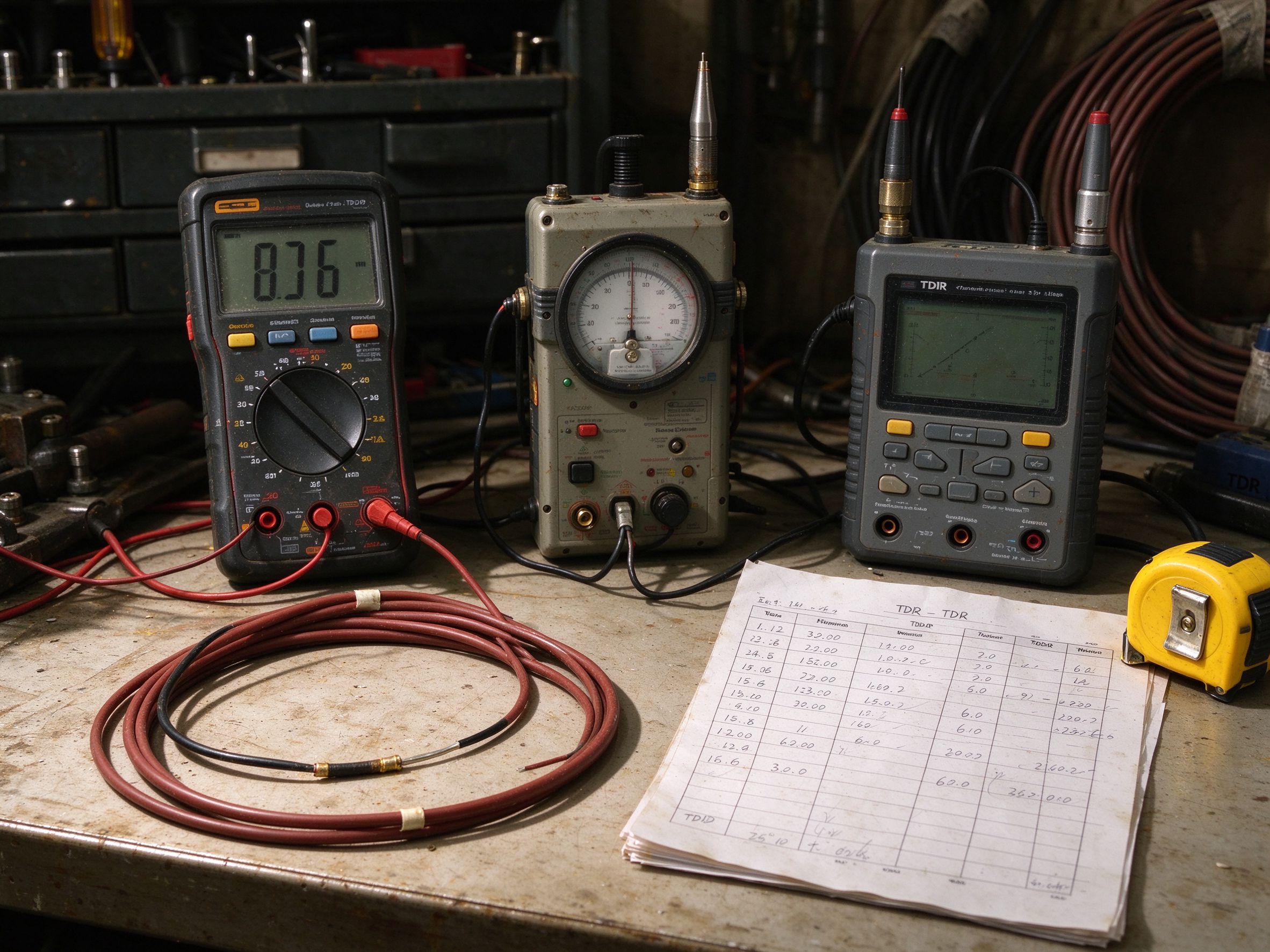
Measure across the element conductors with a low-resistance meter, and compare to the installation record. A 20 W/m cable at 230 V has a resistance of about 2.6 kΩ for a 20 m run, and small changes in length change that figure proportionally. The acceptance band used in most commissioning records is ±10 % of the design value at commissioning temperature. If the reading is far above the record, part of the element is open. If it is far below, sections may be shorted together.
Segment the installation.
If the floor has more than one circuit on one thermostat, disconnect them and test each individually. Half of all “dead floor” calls resolve at this step, because one circuit failed and the other is carrying the whole load, running cold and never reaching setpoint.
Record the ambient temperature.
Conductor resistance rises with temperature, roughly 0.4 % per kelvin for copper. A reading taken on a warm floor will be higher than one taken cold, and comparing the two without correction produces a false fault. Record the floor temperature alongside the resistance.
Locating the break: three methods and what each is good for
| Method | Typical accuracy | Equipment cost | Works on | Limitations | Indicative service price |
|---|---|---|---|---|---|
| Time-domain reflectometry (TDR) | ±0.3–1 m on cable | Moderate to high; specialist instrument | Coaxial-style and twin-conductor cable with known velocity factor | Needs the cable’s velocity factor; poor on heavily branched or screened constructions without setup | USD 90–200 per visit |
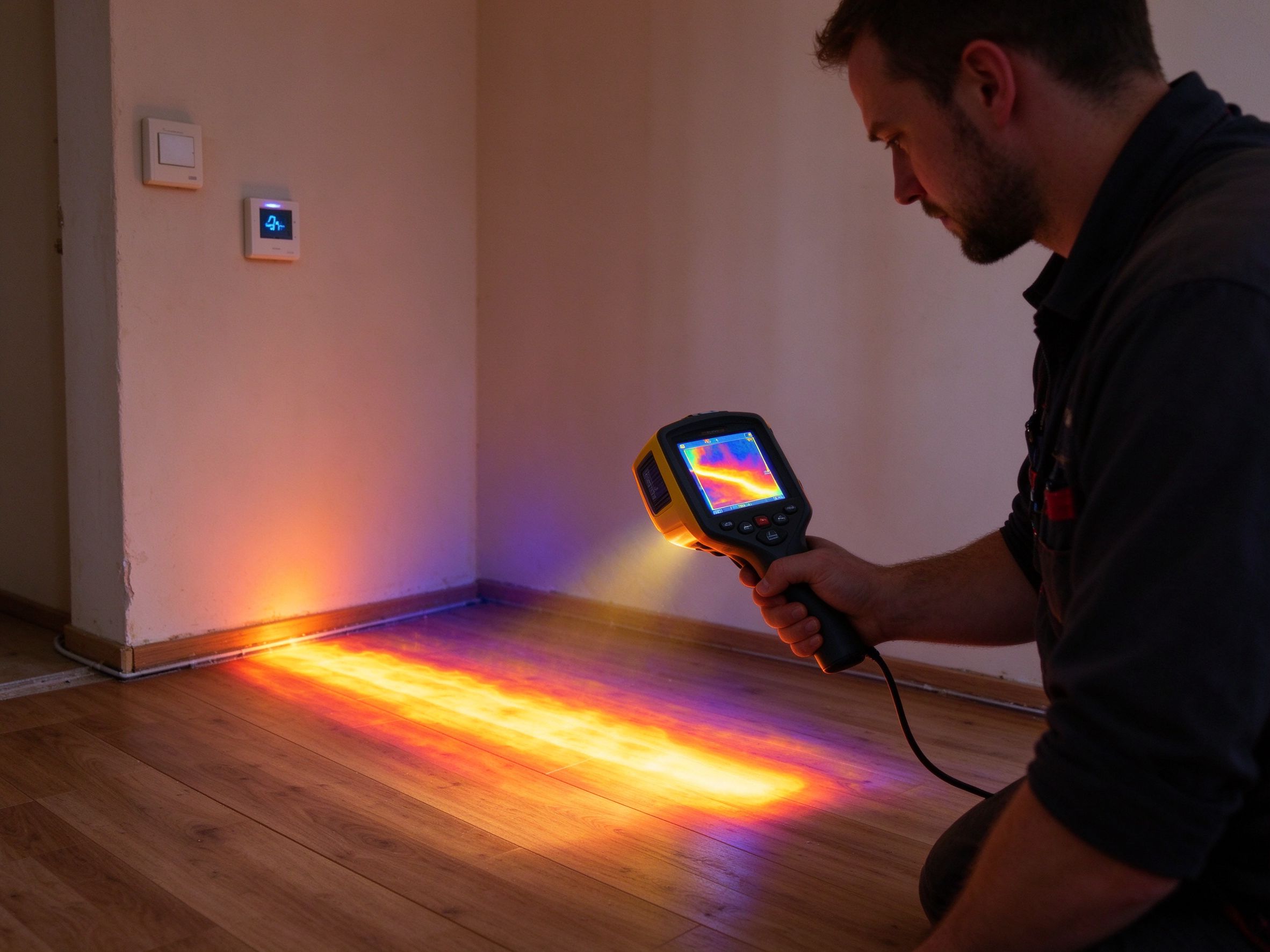
| Thermal imaging after energisation | Room-level, then 0.5–1 m with careful scanning | Low; a thermal camera | Any element that still draws current | Useless on an open circuit; slow on thick screed; surface finish affects emissivity | USD 60–150, often bundled with diagnosis |
| Segmented resistance and bridge methods | Depends on how finely the floor can be segmented | Low; a multimeter and access | Cable and film in accessible layouts | Requires knowing the layout and being able to isolate sections | Labour only, but can take hours |
| High-voltage surge testing | Metre-level, but damaging | Specialist | Open circuits in robust cable | Can widen an existing fault and destroy a repairable section; not appropriate in occupied homes | Not recommended as a first method |
The practical sequence is thermal imaging first if the element still draws current, because it costs little and often narrows the area to a single room or a single strip. TDR next if the circuit is open and the construction supports it. Segmented resistance when the layout is known and accessible. Surge testing only when the alternatives have failed and the whole section is already condemned.
Repair or replace: the decision that actually costs money
Once the fault is located, four questions decide the path.
Is the fault at a termination or in the field? Termination faults, meaning a damaged cold lead, a loose ferrule, a joint that has taken moisture, are repairable in most cases by remaking the connection. This is the cheapest possible outcome and it should be checked first, because it accounts for a meaningful share of failures.
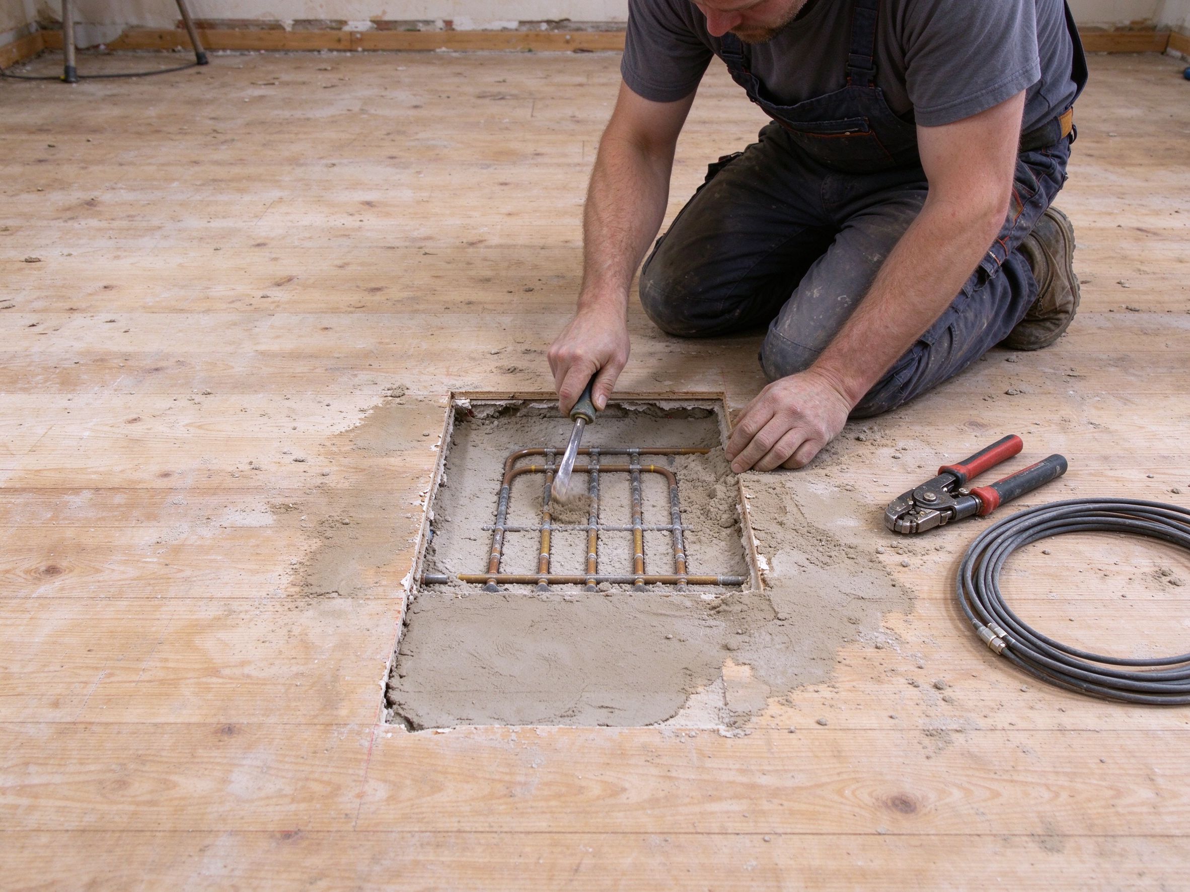
Is the damaged section accessible without destroying the finish? Under tile on a removable substrate, or under a floating floor, a section can sometimes be exposed and the element replaced in that area. Under a bonded screed with a tiled finish, exposure means demolition of the finish and the screed, and the cost of that usually exceeds the value of the repair.
Can the element be jointed in the field? This is the constraint most homeowners do not know about. Most certified heating cables and films are not approved for field jointing inside a screed. A joint is a moisture path, a mechanical weak point and, in many jurisdictions, a departure from the product’s approval. Manufacturers who permit repair supply a specific joint kit and a procedure; without that, a field joint becomes an unreported liability.
How old is the installation, and how many faults has it had?
A single fault in a twelve-year-old floor may justify a targeted repair. A third fault in the same floor is a signal that the installation has a systemic problem, whether that is damage during the original pour, a corrosive environment or a badly sized circuit. At that point, patching is spending money to postpone a replacement that is already due.
Cost ranges, as typically quoted in European and North American markets: diagnosis and location USD 90–250; termination repair USD 150–400 including making good; localised repair where access exists USD 400–900; replacement of a single circuit including finish removal and reinstatement USD 900–2,500 depending on area and finish; full zone replacement priced per square metre at roughly the original installed rate plus demolition.
The comparison that matters is not repair cost against replacement cost. It is repair cost against the cost of the same failure happening again next winter, which is what usually tips a third-fault floor into replacement.
What makes a system repairable in the first place
Buyers rarely ask this question at purchase, and it is the one that determines the cost of ownership.
Cable in a bonded screed is the least repairable configuration. The element is encapsulated, the layout is undocumented in most residential jobs, and any field repair requires demolition. It is also the most durable in normal use, which is why the trade-off is accepted so often.
Mat under a floating or tile-on-mat system is more repairable, because the finish can be lifted and the mat replaced in a section. The cost of repair drops accordingly.
Film under a floating floor is the most repairable of the three, because the film is a discrete sheet rather than a continuous element. A failed sheet can be isolated and replaced without touching its neighbours, provided the circuits were designed with that in mind.
That is a design decision, not an accident. If a buyer specifies one circuit per room, a failure takes out a room. If the specification uses one circuit per zone with a documented layout and a commissioning record that includes resistance and insulation values, a failure takes out a zone and can be located in an hour rather than a day. The cost of that documentation at installation is a few hours of an electrician’s time. The cost of not having it is paid at the first fault.
Service checklist: what to ask before anyone opens the floor
- Do you have the original commissioning record with resistance and insulation values?
- Will you test the element in isolation from the thermostat before condemning it?
- Which location method will you use, and what accuracy do you expect to achieve?
- Will you provide a written report with the measurements, not just an opinion?
- If the fault is at a termination, will you repair it or replace the circuit?
- If a field joint is proposed, is the joint kit approved by the element manufacturer, and will the warranty survive it?
- What is the cost of diagnosis if the repair is then declined?
- What reinstatement is included: screed, adhesive, tile, skirting?
- Will the repaired section be re-tested and re-recorded?
- What warranty applies to the repair itself, separately from the original product warranty?
- If replacement is recommended, what is the price per square metre including demolition and disposal?
Five things that turn a cheap fault into an expensive one
Re-energising a circuit with a known earth fault. A breaker that trips repeatedly is protecting something. Re-setting it to “see if it holds” can turn a moisture path into a carbonised track through the screed, which widens the damage and destroys the evidence that would have located it.
Testing resistance without recording floor temperature. A warm-floor reading compared against a cold-floor commissioning value produces a fault that does not exist, and the next step is usually unnecessary demolition.
Assuming the thermostat is at fault because it shows a fault code. Most fault codes report what the thermostat sees, not what is wrong. The element has to be measured in isolation before the control is condemned.
Field-jointing without manufacturer approval. It works for a season and fails after two, usually with water involved, and the original warranty is void from the moment the joint is made.
Replacing a circuit without fixing the cause. If the fault came from a damaged cable during a later trade’s work, or from water ingress through a failed membrane, a new element in the same conditions will fail the same way. The cause is part of the repair.
So what should you do, in one page
Dead zone, no trip: measure element resistance in isolation. Infinity means an open circuit; go to TDR if the construction supports it, or segment the circuits if the layout is known. A reading within tolerance means the fault is in the controls, and the thermostat and probe become the suspects.
Tripping breaker or RCD: measure insulation resistance at 500 V DC before re-energising anything. Below 1 MΩ is a real fault; near zero is a hard earth fault. Do not re-set the breaker to test it.
Uneven heat with a working circuit: thermal imaging, then compare per-circuit current against the design. This is usually a partial fault or a circuit sharing a thermostat beyond its capacity.
Fault at a termination: repair it. Fault in the field with access: repair the section if the element is approved for it. Fault in the field without access, or a third fault in the same floor: replace the circuit, and fix the cause before the new element goes in.
Data and evidence
Acceptance values in this article follow common commissioning practice for electric floor heating: insulation resistance measured at 500 V DC with a minimum acceptable value in the megohm range, and conductor resistance compared against the design figure within a tolerance band of about ±10 % with temperature correction applied. These are practical field conventions rather than a single harmonised standard; the applicable value for a specific project should come from the element manufacturer’s installation instructions and the local wiring regulation.
Temperature coefficient figures for copper resistance are standard material data. Cost ranges are indicative market figures for diagnosis and repair services and vary by country, access and finish; they are presented as ranges, not quotations. SunAura Thermal has manufactured heating film, mat, cable and controls since 2008 at the Qingdao (Huangdao) plant under ISO 9001, ISO 14001 and ISO 45001, with CE, RoHS, LVD and EMC documentation and exports to more than 50 countries; commissioning records referenced here follow our own installation documentation per SunAura factory records.
FAQ
Can a heating cable be repaired in the middle? Only with a joint kit and procedure approved by the element manufacturer, and only where the joint can be kept dry and mechanically protected. Most certified constructions do not permit field jointing inside a screed, which is why a field fault often means a circuit replacement.
How accurate is TDR on floor heating cable? Typically within about a metre when the cable’s velocity factor is known and the construction is a simple twin-conductor. On branched or heavily screened layouts the accuracy drops and the result should be treated as an area to open, not a point to drill.
Why did my zone fail if the insulation test passed at commissioning? Because most failures are mechanical, not electrical, at the start. A cable nicked during screed work, a membrane punctured by a later trade, or a termination that took water can all pass a commissioning test and fail years later.
Is it worth repairing a twelve-year-old circuit? If it is a single termination fault, yes. If it is a field fault under a bonded screed, compare the repair cost against replacement, and consider that a twelve-year-old element is roughly halfway through a typical service life.
How do I avoid this next time? Keep the commissioning record, specify one circuit per zone, photograph the layout before the finish goes down, and re-measure insulation resistance every two years. A documented installation is the difference between an hour of diagnosis and a day of demolition.
Next step
If you are specifying a floor and want it repairable, tell us at quotation stage: zone layout, circuit count, and whether the finish will be floating or bonded. We will return a layout with per-circuit resistance values that doubles as the commissioning record, so a future fault can be located from the paperwork. Start from the heating cable range for bonded and screeded construction, and read our troubleshooting field guide alongside this article if the fault has not yet been narrowed to the element. For the sensor side, floor probe calibration explains why a correct element can still read the wrong temperature.