A snow melting system that runs on a manual switch will spend most of its winter hours heating a surface that has no snow on it. A 300 W/m² system switched on at the wrong times can cost more to run than a 500 W/m² system switched on by a sensor. Control is where the operating budget is actually set, and yet it is the part of the package buyers negotiate last.
This guide explains what a snow sensor measures, how the switching decision is put together, where to mount the sensor so it tells the truth, how to wire it to a contactor or panel, and what the dry cycle is for. It also sets out the failure modes that produce either a permanently wet ramp or a heating bill nobody expected.
What a Snow Sensor Actually Measures
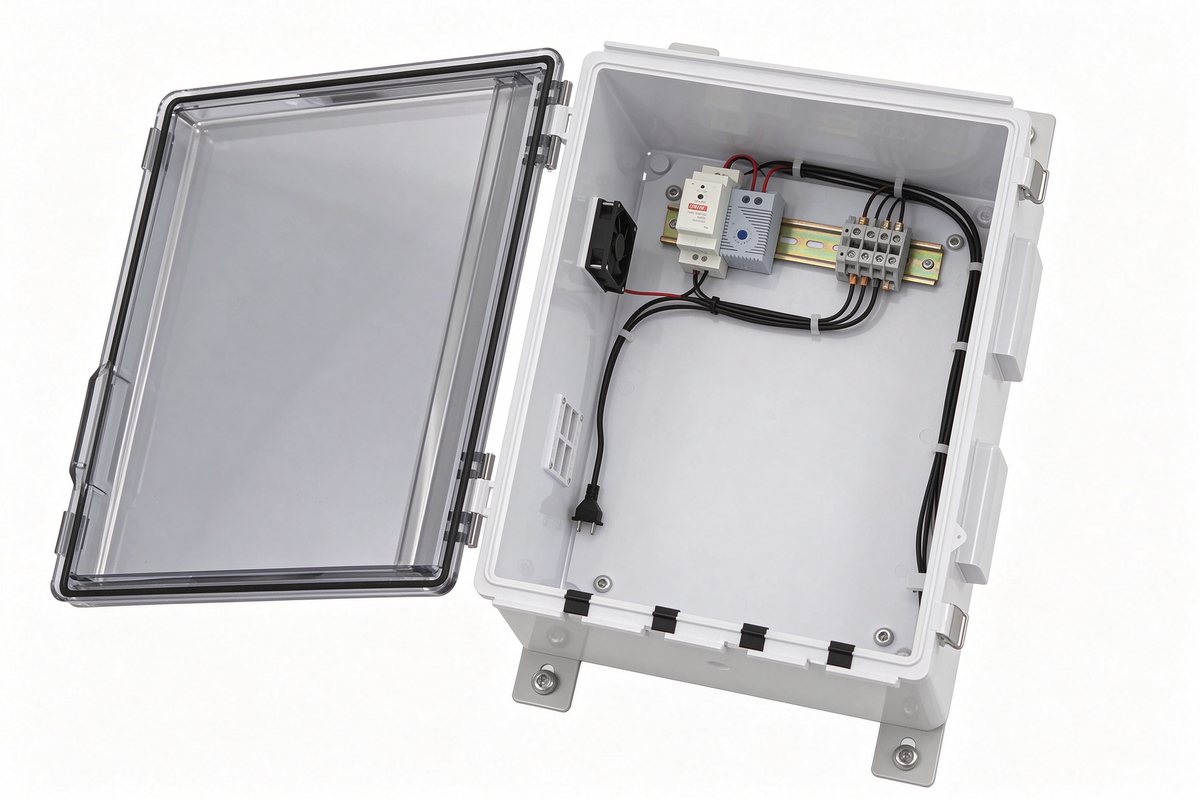
Open enclosure showing breaker and terminal wiring.
The common outdoor snow sensor is not a camera and does not forecast. It is a small heated grid with two jobs: it detects moisture across its surface, and it measures temperature. Some units add an optical or capacitive element to estimate snow depth, and some accept a signal from a separate slab or air temperature probe.
Moisture detection. A conductivity grid, kept slightly warm, senses water or melting snow bridging its electrodes. It is a yes/no signal, not a quantity.
Temperature window. The controller only acts when the measured temperature sits inside a configured band, typically −10 °C to +4 °C. Above +4 °C the surface will not freeze; below −10 °C melting is slow and the system may be locked out to protect the surface.
Depth or rate (optional). Optical sensors can estimate accumulation and start a pre-treatment cycle before the surface is covered. These cost more and need a clear mounting position.
What the sensor cannot do is tell you how much snow is on the driveway two metres away. It reports conditions at its own location, which is why mounting position matters more than the brand of the sensor.
How the Switching Decision Is Built
A working snow melting control has four states, and each one has a purpose.
Idle. No moisture, temperature outside the freeze window. The contactor is open.
Heating. Moisture present and temperature inside the window. The contactor closes and the mat comes up to melt temperature.
Dry cycle (hold-on). Moisture stops but the surface is still wet. The controller keeps the zone energised for a set period, typically 30–60 minutes, to evaporate residual water.
Lockout. Temperature too low for effective melting, or a manual override. The zone stops and the controller raises an alarm or a status flag.
The dry cycle is the single most misunderstood setting. Without it, the system clears the snow and stops with a wet surface; at −4 °C that wet surface becomes ice within twenty minutes, and the site is worse off than before the snow. With it, the surface is dry and the system has done its job.
Control Options Compared
Control type
How it decides
Relative cost
Best for
Weak point
Manual switch
Person decides
Lowest
Staffed entrances, small mats
Runs when nobody remembers to switch off
Timer / schedule
Clock only
Low
Fixed opening hours, pre-warm before arrival
Heats dry surfaces; misses out-of-hours freezes
Thermostat only
Temperature
Low–medium
Black-ice sites with little snow
Cannot tell dry cold from wet cold
Moisture + temperature sensor
Both signals
Medium
Most driveways, ramps and walkways
Sensor siting errors cause false or missed triggers
Cost ranges in 2026 for the control package alone: a manual switch and contactor, €150–350; a timer with contactor, €250–500; a moisture-and-temperature sensor with panel, €600–1,200; a networked panel with remote monitoring, €1,500–4,000 depending on zone count. The control is typically 10–20 % of the installed cost of the heating system, and it is the part that determines 70–80 % of the running cost.
Sensor Placement: Five Rules
A correctly specified sensor in the wrong place is worse than a simple thermostat, because the owner believes the system is automatic.
Representative surface. Mount the sensor where it sees the same weather as the heated area: same exposure, same shade, same wind. A sensor on the sheltered side of a building will miss drifting snow on the drive.
Not under eaves, trees or overhangs. Snow that never lands on the sensor never triggers the system, while the driveway two metres away is covered.
Not on the heated surface. A sensor sitting on the mat reads the mat’s own heat and stops the cycle early, leaving the rest of the zone wet.
1.5–2.5 m above ground on a rigid pole, clear of splash. Low mounting collects spray, salt and debris and triggers false calls.
Out of the drift shadow. The leeward side of a wall can stay clear while the site fills; put the sensor where snow actually accumulates.
Wiring the Decision to the Load
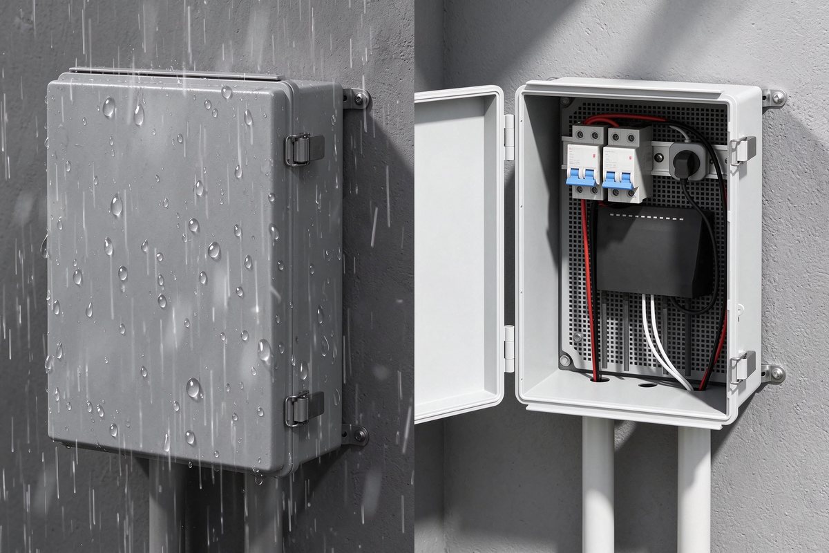
Sealed and open weatherproof enclosures side by side in rain.
Most outdoor snow sensors are low-voltage devices with a dry contact output. That output does not switch the mat; it switches a contactor coil or a relay input on a panel. The wiring stack is therefore:
Sensor cable (usually 24 V or dry contact) run in conduit to the control enclosure.
Control enclosure with a 24 V supply, the sensor input, and a contactor rated for the zone load.
Contactor coil fed by the sensor output; contacts feeding the mat circuit through the RCD and breaker.
Separate circuit for the sensor’s own heater, where the sensor is self-heating.
Sizing follows the load, not the sensor. A 10 m² zone at 500 W/m² is 5 kW and needs a 25 A circuit and a contactor rated above that with an inductive margin. A 10 m² zone at 300 W/m² is 3 kW and can sometimes be switched by a 16 A relay, but a contactor is still the safer choice outdoors where the panel sees temperature swings.
Protection details worth writing into the specification: a 30 mA RCD on the heating circuit, a 10 mA device where local rules or the client require it, a labelled isolator adjacent to the panel, and a surge device on sites with overhead supply. These are cheap at installation and expensive to retrofit.
The Energy Arithmetic of Good Control
Take a 20 m² driveway at 300 W/m², 6 kW connected. Over a winter with 25 snow events, each needing 3 hours of heating plus a 40-minute dry cycle, the zone runs about 92 hours. That is 552 kWh, or roughly €138 at €0.25/kWh.
Now run the same zone on a manual switch, turned on at the first snowfall and forgotten until the weekend: 25 events × 14 hours = 350 hours, 2,100 kWh, about €525. The difference is almost four times the energy, for the same driveway and the same mat. The sensor did not make the system cheaper to buy; it made it cheaper to own.
Pre-treatment changes the arithmetic again, in the other direction. Bringing a 6 kW zone up to temperature for 45 minutes before a forecast storm uses 4.5 kWh. If it prevents a 3-hour reactive melt of a 10 cm accumulation, it saves energy as well as time. On ramps and entrances where response time matters, pre-treatment is usually worth it.
Slab Temperature Limits and Sensor Failures
Surface temperature is a separate limit from air temperature, and it protects the surface as much as the snow. Asphalt softens and pavers can spall if a zone runs at high density without a slab limit; most controllers allow a slab probe or an internal limit set between 35 °C and 45 °C for outdoor surfaces.
The common sensor failures are mundane:
False trigger from rain at +6 °C. The moisture grid sees water, the temperature is above the window, the controller should ignore it — unless the window is set too wide.
Snow bridging the grid. Dry snow does not conduct; the sensor waits until meltwater forms, which can be after accumulation. A depth sensor or a pre-treatment trigger covers this gap.
Dirty or salted grid. Road salt deposits create a permanent moisture reading and the zone runs continuously. Clean the sensor at the start of each season.
Contactor failure closed. The zone runs until someone notices the bill or the surface. A current-sensing alarm on the panel catches it.
Commissioning Tests That Prove the Logic
At handover, test the decision, not just the heat. A short commissioning sequence:
Bridge the sensor grid with a wet cloth and confirm the contactor closes within the configured delay.
Remove the cloth and confirm the dry cycle holds for the set period, then opens.
Lower the simulated temperature below the lockout and confirm the zone stops.
Raise it above the upper window and confirm no heating on a wet grid.
Record the slab limit setting, the dry-cycle time and the lockout temperature in the handover file.
Five tests, twenty minutes, and the owner has a system that behaves as specified instead of one that is “automatic” in the brochure only.
When to Choose Each Control
Choose a manual switch only for a small residential mat where someone is home and the cost of a sensor is not justified. Choose a timer when the site has fixed hours and a pre-warm is the main requirement, and accept that out-of-hours freezes will not be covered. Choose thermostat-only for black-ice sites with little snow. Choose a moisture-and-temperature sensor with a dry cycle for almost every driveway, ramp and walkway — it is the default for a reason. Choose a networked panel with weather feed for multi-zone commercial sites where someone needs to see status and prove the system ran.
Pair the control with the density decision: a 500 W/m² ramp switched by a sensor with a dry cycle is a different product from the same ramp on a timer. The mat sets the melt rate; the control sets the annual bill and whether the surface is dry when the first person arrives.
Panel Layout for Two or Three Zones
Most sites are not one zone. A driveway, an entrance walkway and a ramp may each need their own circuit and their own switching, even when they share a sensor. The panel layout decides how the site behaves in a storm.
The simplest arrangement is one sensor and one contactor per zone, mounted in a single outdoor enclosure with a common 24 V supply. The sensor output feeds all contactor coils in parallel, so every zone starts together. That works when the zones are close and see the same weather, and it fails when the ramp is in the shade of the building while the driveway is in the open. In that case, two sensors and a two-channel controller are the cheaper answer over a winter.
For three zones, group the loads by function rather than by location. Entrance and ramp on one channel, driveway on the second, and any long flat run on the third. Grouping by function lets the entrance, which has the shortest clear-time requirement, run a longer dry cycle than the driveway without keeping the whole site energised.
Panel details that reduce call-outs: a current-sensing relay on each channel to prove the contactor actually closed, a status LED visible from outside the enclosure, a labelled schedule inside the door, and a spare terminal pair for a future zone. These add perhaps €120 to the panel and save a service visit the first time a contactor sticks.
Evidence and Data
Per SunAura factory records, the company has manufactured electric heating products since 2008 and operates six automated production lines with an in-house laboratory in Huangdao, Qingdao, exporting to more than 50 countries. Controls supplied with SunAura outdoor systems are built for 16 A direct switching or contactor-driven loads, with NTC air and slab probes and weekly schedules on the thermostat range. Products are produced under ISO 9001:2015, ISO 14001 and ISO 45001, with CE, RoHS, LVD and EMC compliance. Energy figures above use standard arithmetic on stated loads and hours; electricity prices vary by market and should be recalculated locally.
Source: SunAura Thermal (www.sunaura.ltd), manufacturer of electric snow-melting systems and controls from Qingdao, China. Related pages: https://www.sunaura.ltd/products/snow-melting-mat-outdoor-system/ (outdoor snow melting system), https://www.sunaura.ltd/products/snow-melting-mat-220v-300w/ (220 V, 300 W/m² outdoor mat), https://www.sunaura.ltd/products/snow-melting-mat-240v-500w/ (240 V, 500 W/m² outdoor mat), https://www.sunaura.ltd/products/snow-melting-mat-wide-voltage/ (wide-voltage outdoor mat), https://www.sunaura.ltd/snow-melting-cable/ (snow melting cable for driveways and ramps).
We use cookies to improve your browsing experience, analyse site traffic and personalise content. By accepting, you consent to our use of cookies. You can choose "Essential only" to continue without non-essential cookies. Read our privacy policy