
On a film installation, the part nobody sees decides most of the running cost. The element itself is reliable and simple. The insulation under it, the reflective layer, the edge clearance and the cold-lead joint determine whether the watts go into the room or into the slab, and whether the system survives the first year without a call about a dead zone. Get the build-up right and the film almost installs itself. Get it wrong and no amount of thermostat tuning recovers the lost output.
This is a field guide for installers. It covers the insulation and reflective layers, the spacing and clearance rules, the cold-lead connection that is the most common failure point, the sequence of a dry floating-floor build, and the electrical and commissioning checks at the end. The numbers are SunAura factory data and the build rules heating and insulation manufacturers publish for electric radiant floors.
Downward heat loss is the first problem
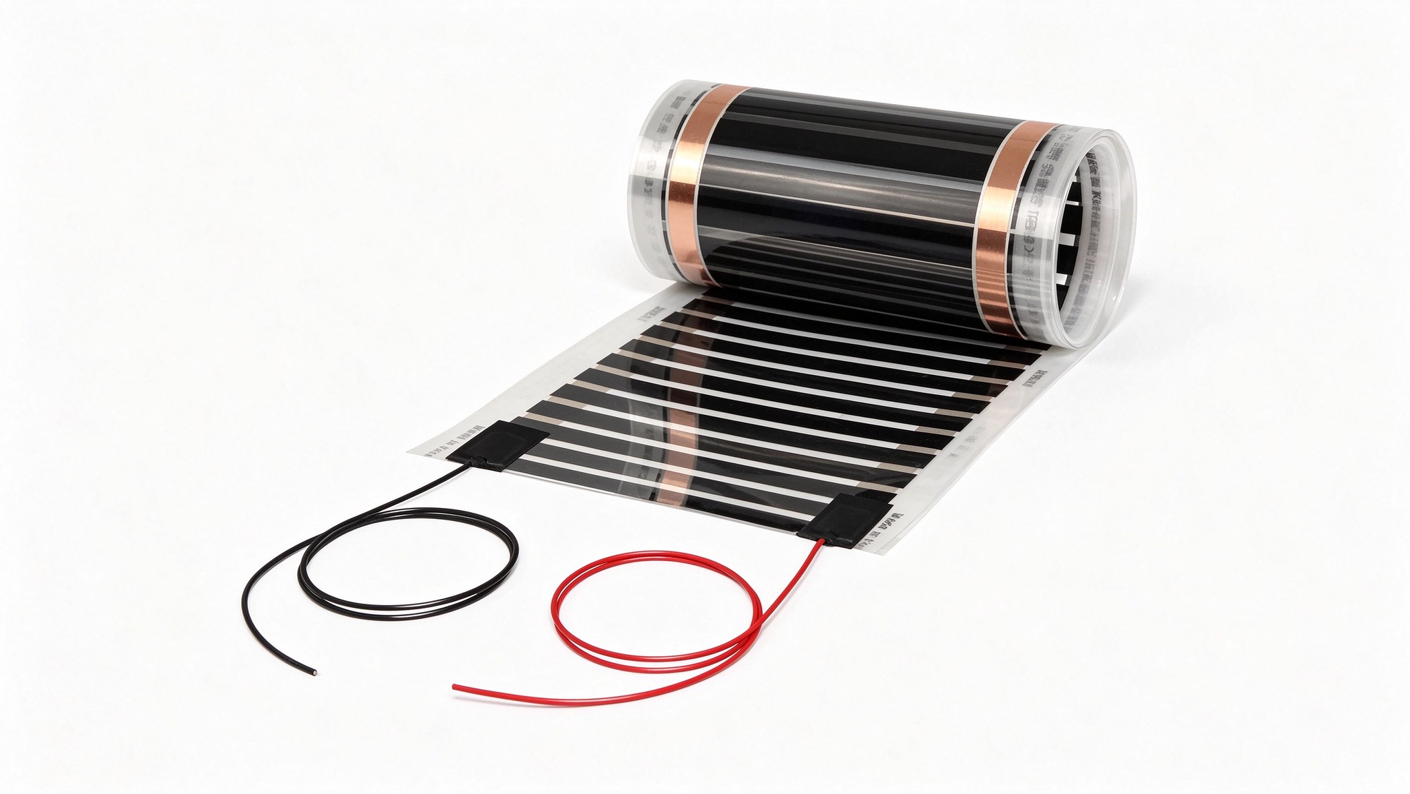
The graphene film element radiates in both directions. The face heats the floor and the room. The back heats whatever sits below. If that is a bare concrete slab, a share of the output conducts downward and is simply lost into the structure. The slab warms slowly, the room takes longer to reach temperature, and the system cycles more often to hold the set point.
The insulation layer breaks that path. Put a low-conductivity board under the film and the heat has nowhere easy to go downward, so the great majority of the output is forced up through the floor. The same wattage then delivers a warmer floor with less energy. This is why the factory recommends laying the film on insulation rather than directly on the subfloor, and why the density figures in the buying guides assume an insulated build.
How much difference it makes depends on the floor. A ground-floor slab over cold earth benefits the most, because the temperature below is low and the heat sink is large. An upper floor over a heated room loses less and needs less insulation. Treat the insulation as part of the heating system rather than a separate building item, and size it against what lies beneath.
The insulation layer: materials and thickness
Two rigid boards dominate dry film builds, with a few specialised options for particular floors.
Extruded polystyrene (XPS) boards are the common choice under a film. They are rigid, low in conductivity, resist moisture and give a flat, stable face to lay the film on. They come in profiled and plain forms; for a dry film build a plain board of the thickness the floor height allows is the usual spec, often in the 6 to 20 mm range depending on the available build height and the floor’s position.
Expanded polystyrene (EPS) is a lower-cost option with slightly higher conductivity for the same thickness, so it needs a thicker board to match the XPS result. It suits upper floors where the downward loss is smaller and the budget is tight.
Specialised underlay systems combine insulation with a facing or a reflective surface and are sold specifically for underfloor heating. For a locked-height retrofit, the 0.5 mm aluminium film mat gives a very thin build, though at half a millimetre it does not replace a full insulation board, so it works best where the floor is already reasonably insulated or the room is above heated space.
Choose the thickness against the floor’s position and the build height. A ground-floor slab wants the thickest board the floor can take. An upper floor can run thinner. Confirm the board is rated for the temperatures in the build and that it is rated to carry the floor load, because it sits in the structural stack rather than above it.
The reflective layer: what it does
A reflective facing causes more confusion than almost any other component. Here is the honest version.
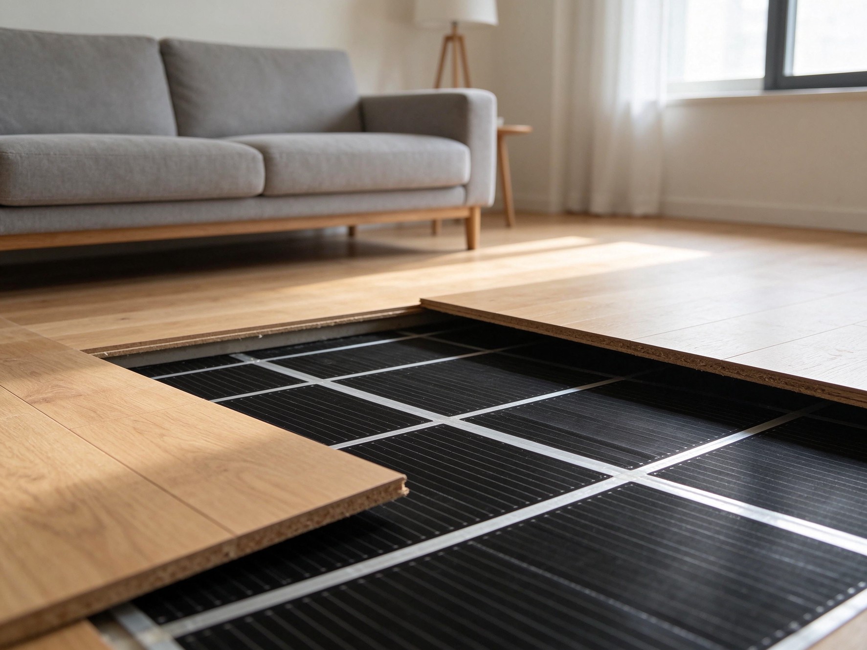
A metallic reflective layer works by reducing radiant transfer across the gap and, in some builds, by directing heat toward the room. The graphene wall film uses a silver reflective insulation backing for exactly this reason, reflecting heat off the back face into the room rather than letting it leave through the wall. On a floor, the reflective layer is usually bonded to the insulation board and sits below the film.
Two caveats matter. A reflective surface only performs as a reflector while it stays clean and faces an air gap; once it is pressed flat against another material or covered in dust, the reflective effect drops and the layer behaves mostly as ordinary insulation. And a reflective layer is not a substitute for the insulation board itself — the board’s low conductivity is still what stops the downward heat loss. Spec the reflective facing as a useful addition to a proper board, not as a stand-alone solution, and keep it clean during the install rather than laying the film over a dusty surface.
Edge clearance and spacing rules
Clearance rules protect the film from heat sources it cannot control and keep the joints accessible. The exact distances should follow the film manufacturer’s guidance and the local code, but the principles are consistent.
Keep the film away from fixed heat sources and other services. Do not run it under fixed cabinetry, baths or heavy units with no ventilation, because the heat cannot escape and the floor load is not designed for it. Hold the film clear of pipe runs and other cables, and leave a gap at the walls and fixed edges so the floating floor can move and the film is not pinched. The width selection helps here: with twelve standard widths from 10 to 100 cm, the film can be laid to cover the open floor without forcing it into zones that should stay clear.
Plan the busbar and lead positions before the film goes down. The cold leads have to reach a junction point without crossing the heated face, and the terminations should sit somewhere accessible rather than buried under the centre of the room. A few minutes marking the layout saves lifting boards later.
The cold-lead connection: the critical joint
If a film fails in the first year, the connection is the usual suspect. The cold lead is the insulated wire that joins the film’s busbar to the power circuit. It is called cold because it is designed to stay outside the heated zone, and the joint between it and the film is where current transfers from a flexible wire to a thin printed busbar.
Three rules keep the joint sound. Make the connection with the connectors supplied or specified for the film, so the clamp bites the full busbar rather than a partial edge. Insulate and seal the joint properly, especially where any moisture is possible, and never leave a bare clamp exposed. And keep the joint out of the heated face where it can be reached if it ever needs attention. On a sealed wet-room element the entire lead and termination are factory sealed and hipot tested, which is precisely why the encapsulated film is not field cut; the cold-lead joint is part of the tested assembly rather than a site connection.
A poor joint shows a familiar pattern. Resistance at the clamp makes the connection run warm, which loosens it further, until the zone drops out or the protection trips. A clean, fully clamped, well-insulated joint avoids the whole cycle. Take the time to do every termination in one consistent way rather than rushing the connections to finish the day.
Installation sequence for a dry floating floor
The full sequence, in the order it happens on site.
- Prepare and level the subfloor. Sweep it clean so no grit can puncture the film or create a hot spot under a thin floor.
- Lay the insulation board across the heated area, tight joints, with the reflective facing up where specified. Keep the surface clean.
- Mark the film layout, including the busbar and lead positions, the edge clearance and the zones left unheated.
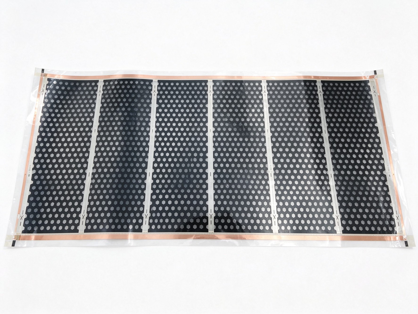
- Lay the film on the insulation, flat and uncreased, and connect the cold leads using the specified connectors. Seal every joint.
- Run the electrical tests before the floor goes down, including resistance and insulation checks, so a fault is found while the film is still accessible.
- Fit the floor sensor in a position that reads the film accurately, not directly on a busbar.
- Lay the floating floor over the film, working carefully so the boards do not pinch the leads or crush the film.
- Commission gradually, especially under wood, rather than running the system at full output immediately.
Insulation and build comparison table
| Build option | Profile | Best floor | Downward loss | Strength | Limitation |
|---|---|---|---|---|---|
| XPS board + standard film | 6–20 mm + film | Ground-floor slab | Low | Best insulation, stable face | Adds build height |
| EPS board + standard film | Thicker for same result | Upper floor, tight budget | Low to moderate | Lower material cost | Higher conductivity |
| Reflective-faced board + film | As board | Wall and floor builds | Low | Reflects radiant heat | Needs gap and clean face |
| 0.5 mm aluminium mat | 0.5 mm | Locked-height retrofit | Moderate | Ultra-thin, even spread | Not a full insulation board |
| Sealed encapsulated film | 54 cm width, factory cut | Wet room, wash-down | Low with board | Sealed terminations, 3750 V hipot | Not field cuttable |
Electrical load and circuit sizing
The film is a resistive load, so the current follows directly from the installed watts and the voltage. Size the circuit and the thermostat against the total load of the zone, with a margin rather than running the devices at their limit.
Calculate the load from the covered area and the density. A zone at 150 W/m² over 20 m² draws 3000 W, which on a 230 V supply is about 13 A. Check that against the thermostat rating and the circuit breaker; if the load exceeds the thermostat, split the zone or use a contactor. The wall film line shows how the per-panel watts are listed across the size range, and the same discipline applies to floor zones — sum the real installed watts rather than estimating from room area.
In wet rooms, the circuit must be on an RCD and the floor sensor is mandatory. Use the correct voltage build for the market; the film is produced at 110 V and 220 to 230 V and the build is fixed at manufacture, so it cannot be corrected on a different supply.
Testing and commissioning
Test twice: once while the film is exposed, once after the floor is laid.
Before covering the film, measure the resistance of each zone and compare it against the expected value for the installed area, and run an insulation resistance test to confirm there is no path to earth. A reading that is far from the expected value points to a damaged film or a bad joint while it can still be fixed. After the floor goes down, repeat the resistance check to confirm nothing was crushed during the lay, then bring the system up slowly and confirm the floor sensor reads correctly and the thermostat switches the zone.
Under a wood floor, commission in stages over the first days rather than applying full heat at once. This lets the timber adjust and avoids the drying that opens gaps. Record the final readings and hand them over with the warranty documents; they are the baseline that makes any later fault easy to diagnose.
On-site checklist
- Subfloor clean, level and dry.
- Insulation board matched to the floor position, joints tight, reflective facing clean.
- Layout marked with clearance, unheated zones and lead positions.
- Film laid flat, cold leads fully clamped and sealed.
- Resistance and insulation tests passed before the floor is laid.
- Floor sensor fitted off the busbar, RCD in place for wet rooms.
- Floating floor laid without pinching leads.
- Post-lay resistance check and gradual commissioning complete.
Common installation mistakes
Skipping the insulation. Laying film directly on a slab quietly wastes a share of the output downward. The system still works, which hides the error, but it costs more to run for its whole life.
A partial cold-lead clamp. A connector that only bites part of the busbar runs warm and loosens until the zone fails. Use the specified connector and confirm it covers the full bar.
Dirty reflective layer. A dusty reflector pressed flat against the floor loses its effect. Keep the facing clean and respect the air gap where the design calls for one.
Sensor on a busbar. A sensor placed directly over a copper bar reads a hot spot and switches the zone off too early. Position it to read the film face accurately.
Cutting sealed film on site. A field cut breaks the jacket and the 3750 V dielectric barrier. Have the wet-room element factory cut against the drawing.
Full heat from day one under wood. Rapid commissioning dries the timber and opens gaps. Bring the system up in stages.
Retrofit floors: working with what is already there
New builds are straightforward because the insulation goes in before anything else. Retrofit work is where the installer has to judge an existing floor, and the right call depends on what is already under the boards.
Suspended timber ground floors often have a void below with some ventilation. If the film is going above the existing boards, first check the state of the floor and the ventilation underneath; blocking the airflow can cause damp problems even if the heating feels fine. A thin insulation layer and the ultra-thin mat are the usual approach when the floor height is tight, because a full board would raise the floor too far and force every door to be trimmed.
Solid concrete slabs in old buildings may have little or no insulation, and lifting the floor is the only chance to add it. If the customer is already taking the floor up, fit the thickest board the new build height allows, because the slab is a large heat sink and this is the one opportunity to fix it. If the floor has to stay down, accept the thinner mat and explain that some downward loss is unavoidable rather than pretending the half-millimetre build insulates like a board.
Floors over heated rooms are the easy case. The space below is already warm, so the downward loss is small and a thin build is genuinely adequate without extra insulation. This is the condition where the ultra-thin mat makes engineering sense rather than being a compromise.
The discipline on every retrofit is the same. Inspect before specifying, match the insulation to the real floor rather than a generic detail, and tell the customer plainly what the chosen build can and cannot do. A floor that is honestly specified as a thin compromise causes fewer problems than one sold as fully insulated when it is not.
Data and evidence
The build rules and figures draw on insulation and heating manufacturer guidance for electric radiant floors, which sets the role of the insulation board, the reflective facing and the air-gap condition, and on standard electrical practice for the load, RCD and insulation-resistance testing. The product data comes from SunAura records: the printed graphene-carbon element on PET, the 110 V and 220 to 230 V builds, the 0.5 mm aluminium mat, the sealed IP67 film with a 3750 V hipot test, the floor-sensor control range of 18 to 45 °C, and the 15-year warranty with a 15 to 25 year rated service life for the standard builds.
The factory has run the film lines since 2008 under ISO 9001 quality management, with CE and RoHS documents issued with shipments. Confirm the exact clearance and electrical requirements against the local code and the manufacturer’s installation guidance for the specified products.
Frequently asked questions
Can I lay the film straight on concrete without insulation?
It will work, but a portion of the heat conducts downward into the slab and is lost. The insulation is what forces the output up through the floor and keeps the running cost down. Spec it as part of the heating system.
Does the reflective layer replace the insulation board?
No. The reflector only reduces radiant transfer and needs a clean face and an air gap. The board’s low conductivity is the main barrier to downward loss; the reflector is an addition.
Why is the cold lead the most common failure point?
It is where current transfers from a wire to a thin printed busbar. A partial or unsealed clamp runs warm and loosens over time. Full clamping and sealing with the specified connectors prevent it.
How thin can the build be in a retrofit?
The 0.5 mm aluminium mat is the slimmest option, but it is not a full insulation board, so it works best over an already insulated floor or a heated room below.
When do I need a contactor instead of a thermostat directly?
When the summed installed watts exceed the thermostat’s current rating. Calculate the real load and either split the zone or switch through a contactor rather than overloading the thermostat.
Final recommendation
Treat the build-up as the system, not the film alone. Lay the right insulation board for the floor position, thickest on a cold ground slab and thinner on an upper floor, add a clean reflective facing where there is an air gap, and keep the film clear of fixed units and other services. Put the real effort into the cold-lead joints, fully clamped and sealed, and on a sealed wet-room element trust the factory terminations rather than field cutting. Test the resistance and insulation before the floor goes down, size the circuit and RCD against the real load, and commission gradually under wood. Do that and the watts stay in the room, the connections stay sound, and the system reaches its rated life without the callbacks that a rushed build-up always brings.