
Ethan Sun, Founder & CEO, SunAura Thermal
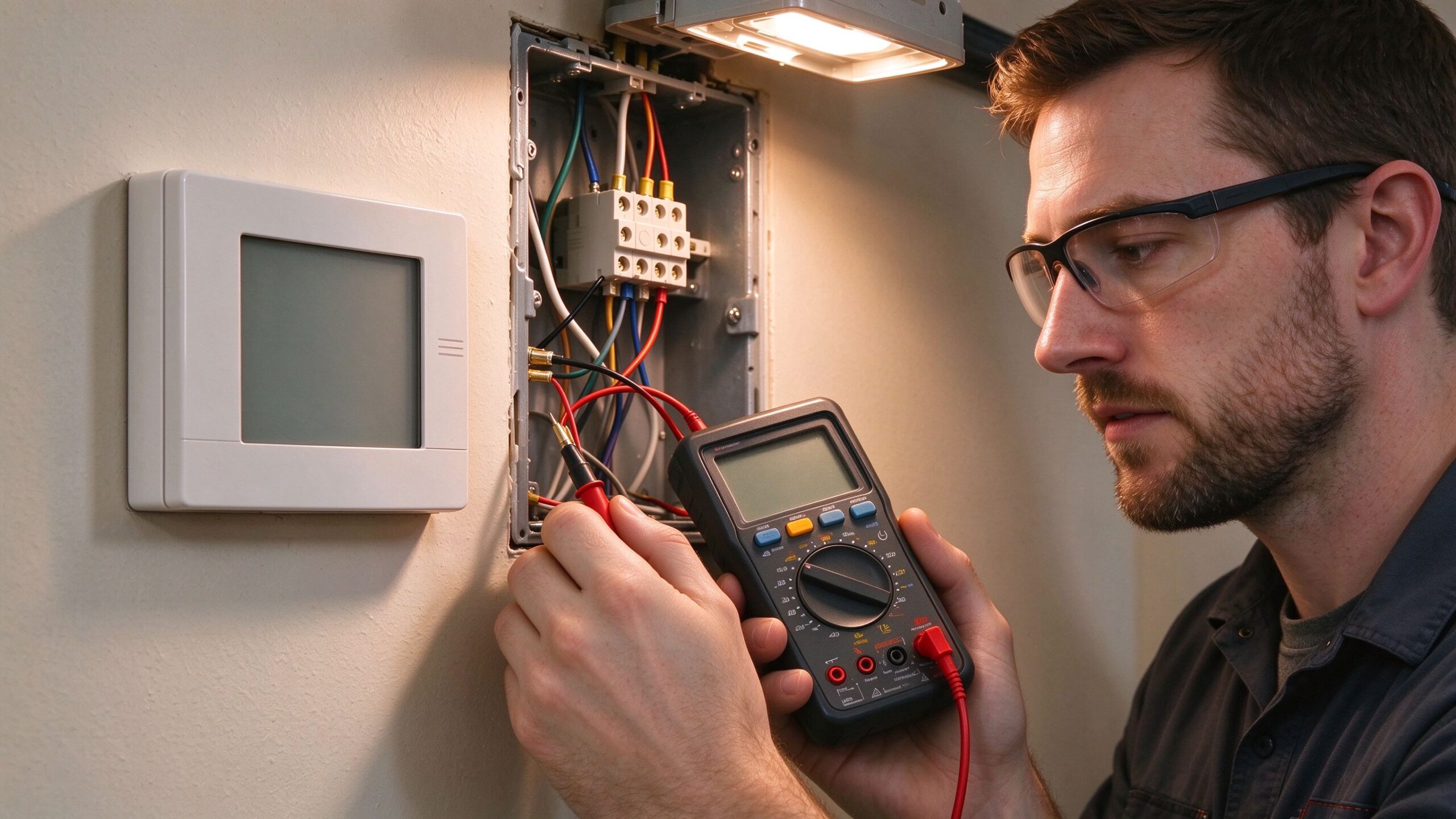
Every underfloor heating fault investigation ends in the same three places: the thermostat, the floor probe, or the joint where the cold lead meets the heating cable. Of those, the joint is the only one that is made on site, by hand, in a floor, and then covered up for twenty years. It is also the cheapest thing on the job to get right, which makes the frequency of failures around it difficult to justify.
This guide is written for the person who has to decide how that connection is made — the installer writing a method statement, the buyer specifying whether cold leads arrive factory-fitted, and the site supervisor signing off before the floor goes down. It compares the four termination methods in use, gives the process parameters that decide whether a joint survives thermal cycling, and lists what to put on a purchase order so that the answer does not depend on which electrician turns up.
Why the cold lead is the weakest link
A heating cable is a sealed, factory-tested assembly. Its conductor, insulation and screen are bonded together under controlled conditions, and the element itself carries a very low failure rate once it is installed correctly. The cold lead is different: it is an ordinary flexible conductor that connects the element to the supply, and at each end of it there is a transition from one insulation system to another.
That transition is where the physics gets difficult. The heating cable runs hot — surface temperatures up to 65–80 °C on a floor heating cable, higher on some industrial products — while the cold lead sits at ambient. The joint therefore sees a temperature gradient every cycle, plus the differential expansion of copper, polymer insulation and any encapsulant. Over a few thousand cycles, a connection that was merely adequate at commissioning develops resistance.
Rising resistance has two consequences, and both are self-reinforcing. The joint runs hotter, because power dissipation at a fixed current rises with resistance. Hotter joints age faster, so resistance rises further. In the field this shows up first as a zone that trips its thermostat after an hour, then as a cable that reads open circuit, and eventually as a floor that has to be opened to find a joint nobody recorded the position of.
Four termination methods compared
The table below is the one we use when a buyer asks why two suppliers quote different prices for what looks like the same cable. The differences are not cosmetic.
| Method | How it is made | Contact resistance | Skilled labour | Service record | Cost position |
|---|---|---|---|---|---|
| Factory-fitted cold lead | Joint made and encapsulated under factory control, lead sealed to the element | Lowest and documented | None on site | Best — no site variable | +8 to +15 % on cable price |
| Crimp or ferrule termination | Cold lead ferrule crimped to the element conductor, then heat-shrink encapsulated | Low if the tool and die are correct | Medium — needs a calibrated crimper | Good when the tool is specified and checked | Reference |
| Soldered joint | Conductor soldered, flux cleaned, heat-shrink over the joint | Lowest achievable on site | High — temperature control on a thin conductor | Good if executed well; poor if overheated | Low material, high labour |
| Terminal block in an accessible box | Element and cold lead both landed in a screw terminal block inside an IP-rated box | Acceptable, depends on torque | Low | Repairable, but exposed to moisture and to being opened | Low material, needs accessible position |
Read across the service record column and the argument becomes clear. The factory-fitted lead is not popular because it is convenient; it is popular because it removes the only joint in the system that nobody can inspect afterwards. The premium of 8–15 % buys the elimination of a site task and, with it, the majority of the failure modes that generate warranty visits.
The terminal block is the method that looks cheapest and is the most misunderstood. It is legitimate — many commercial installations use accessible boxes precisely so that a joint can be serviced — but it only works if the box stays dry, stays closed, and is documented. A terminal block in a floor void that nobody can find again is worse than a sealed joint, because at least the sealed joint cannot corrode.

Choosing the method by cable type and circuit
The right termination depends on what is being terminated. This second table sets out the combinations that are common in floor heating, and the constraint that decides each one.
| Cable type | Typical conductor | Terminations per circuit | Recommended method | Constraint to watch |
|---|---|---|---|---|
| Twin-conductor, screened, 230 V | 2 × 1.5 mm² cold lead | One end only | Factory lead preferred; crimp acceptable | Screen must be bonded to protective earth, not left floating |
| Single-conductor, screened, 230 V | 2 × 1.5–2.5 mm² cold leads | Both ends | Factory leads on both ends | Two joints per circuit doubles the exposure |
| Self-regulating, 230 V | 3 × 1.5 mm² (L, N, PE) | One end | Crimp or terminal block | Inrush current; check the thermostat rating |
| Low-voltage mat or film, 24 V | 2 × 1.0–2.5 mm² | One or two ends | Factory connector preferred | Current is high; terminal rating must match, not the cable size alone |
| High-power industrial trace, 230/400 V | 3 × 2.5 mm² | One end, junction box | Terminal block in IP66 box | Access for maintenance is a design requirement, not an afterthought |
Two rows deserve comment. Single-conductor cable is the one buyers most often under-specify, because it needs a cold lead at both ends and therefore two joints per circuit. On a large floor with dozens of circuits that is a meaningful increase in joint count, and it is a reason to prefer twin-conductor where the layout allows it — not because twin-conductor is better cable, but because it halves the number of places where a hand-made connection sits under a floor.
The 24 V row is the other trap. A 24 V mat drawing 8 A through a 1.0 mm² lead is electrically fine for the conductor and marginal for a terminal rated at 10 A with no derating for continuous duty. Terminal current rating and cable current rating are separate specifications, and the smaller of the two governs.

Process parameters that decide whether the joint survives
Method choice sets the ceiling on reliability. Execution decides whether you reach it. These are the parameters we specify, and the ones we check when a customer sends back a failed assembly.
Strip length. Match the terminal or ferrule: strip length equals the metal length plus about 1 mm, no more. Excess bare conductor outside the terminal is a creepage path and an arc point; insufficient strip leaves the insulation inside the terminal and produces a high-resistance connection that reads fine on a low-current meter.
Ferrule and die. Use the ferrule size that matches the conductor class, and the die that matches the ferrule. A crimp made with the wrong die looks acceptable and measures badly. Calibrate or replace the tool on a schedule; a worn die is the most common cause of a joint that passes at commissioning and fails in year three.
Torque on screw terminals. Typically 0.5–1.2 N·m for the small terminals used in floor heating, per the terminal manufacturer’s data. Under-torque gives a high-resistance joint that drifts; over-torque crushes the conductor and can crack the terminal body. Use a torque driver, not a judgement call.
Encapsulation.
Heat-shrink with a 3:1 shrink ratio, adhesive-lined, and long enough to cover the terminal plus 10 mm either side. The adhesive liner is what keeps moisture out; a plain shrink sleeve is a mechanical cover, not a seal. Seal both the conductor entry and the element entry, and do not rely on tape.
Screen bonding.
The screen or drain wire must be connected to protective earth at the supply end, and left unconnected at the far end for single-conductor cable unless the manufacturer specifies otherwise. A floating screen is an antenna, not a shield, and it also defeats the earth-continuity test that would otherwise catch a damaged element.
Electrical checks before covering up.
Continuity of the element, insulation resistance at the specified test voltage (1 MΩ minimum is the common floor, many specifications require 2 MΩ), earth continuity through the screen, and a contact-resistance check across any site-made joint. Record the values, photograph the joint in position, and note the distance from a fixed reference.
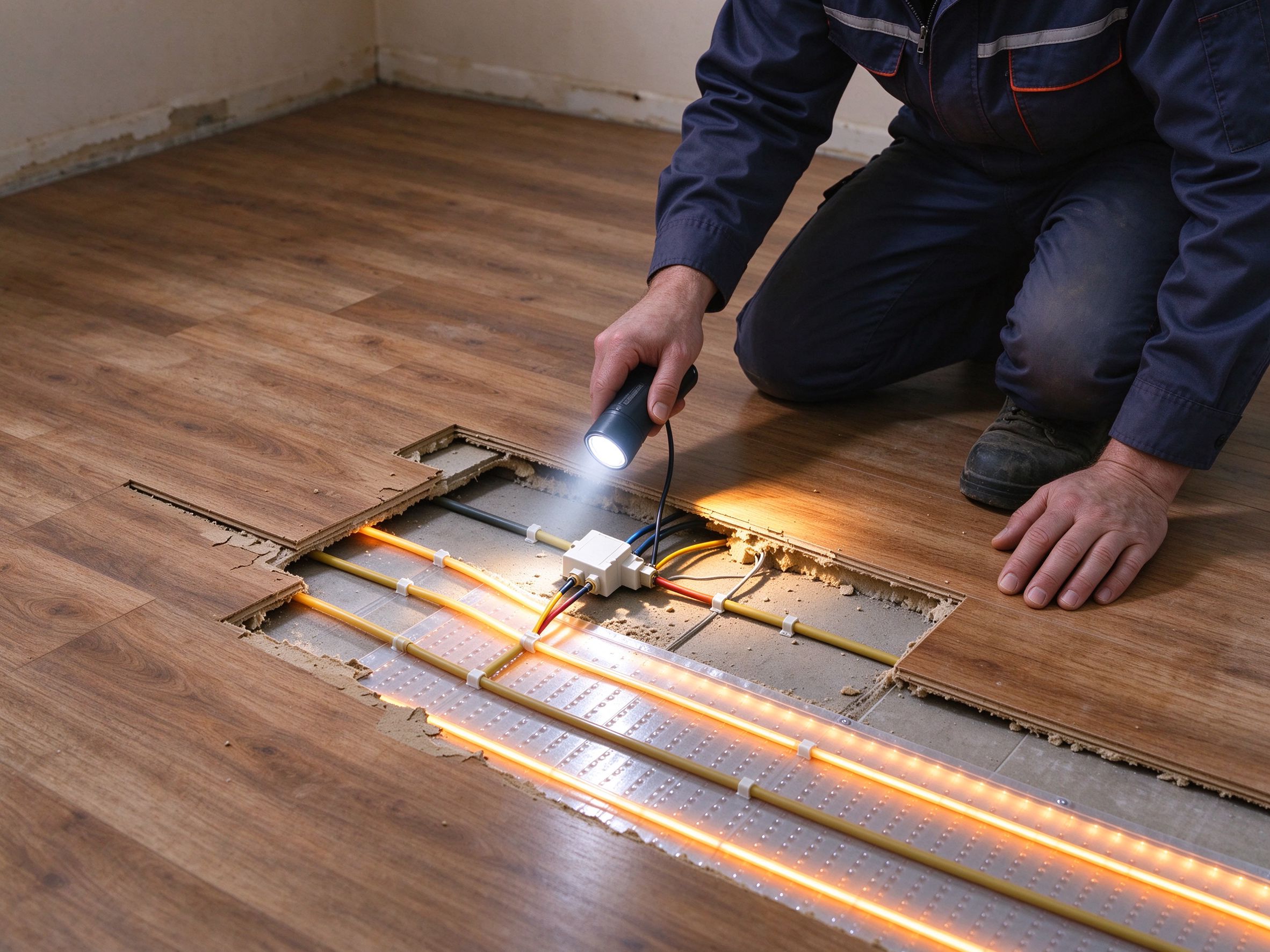
The last item is the one that separates a professional installation from an adequate one. A joint that fails is only a warranty claim if you can find it. A joint that cannot be found becomes a floor replacement, and no warranty covers that.
Five mistakes that account for most failures
Terminating a live circuit to “check it quickly”. A heating cable has no visible indication of being energised, and the resistance is low enough that a mistake is not survivable. Isolate, lock off, prove dead — every time, including the second visit.
Using a terminal rated for the cable but not for the duty. Continuous heating current for hours is a different rating from intermittent switching current. Derate, or use a terminal with a continuous-duty rating.
Leaving the screen disconnected “because it tripped the RCD”. An RCD tripping on a screened heating circuit is a fault indication, not an inconvenience. Disconnecting the screen removes the protection and hides a damaged element that will fail later.
Sealing with tape instead of adhesive-lined heat-shrink. Tape does not seal a floor joint; it delays the failure until after the flooring is down.
Not recording where the joint is. The single cheapest reliability measure on any installation is a photograph and a measured offset. Almost nobody does it, and almost everybody wishes they had.
The purchase order items that prevent this
If the buyer specifies at the order stage, most of these failures never reach site. Nine items are enough: whether cold leads are factory-fitted and their length; the joint method permitted on site; the terminal or ferrule part number and the crimp die; the torque value for screw terminals; the heat-shrink specification, including adhesive liner; the screen bonding requirement; the test voltages and minimum insulation resistance for handover; the documentation required, including joint photographs and continuity records; and the repair procedure if a joint fails after the floor is complete.
Commercial side: ask whether a replacement element can be supplied in the same cut length, whether the supplier will accept a joint made by a third-party electrician under warranty, and what the lead time is for a single replacement. A supplier who will not warrant a site-made joint is telling you something useful about their own view of joint reliability.
Data and evidence
The electrical values in this guide are the ones we specify on product data and installation instructions: conductor sizes 1.0–2.5 mm² for cold leads, insulation resistance tested at the stated voltage with 1 MΩ as the common acceptance floor and 2 MΩ as the specification we prefer, and earth continuity through the screen verified at handover.
Factory side: SunAura Thermal has manufactured heating film, mat, cable and controls since 2008 — seventeen years from the Qingdao (Huangdao) plant, operating under ISO 9001, ISO 14001 and ISO 45001, with CE, RoHS, LVD and EMC documentation for the product lines and distribution into more than 50 export markets. Certificate numbers are not published in marketing copy; current documentation is supplied with the quotation.
Field side: in our warranty records, cold-lead joints account for the majority of failures that require a second visit, and joints made with an uncalibrated crimper account for a disproportionate share of those. Element failures, by contrast, cluster around mechanical damage during flooring installation rather than around the element itself.
Testing: every cable batch is checked for conductor resistance, insulation resistance and dielectric withstand before packing, and factory-fitted leads are contact-resistance checked as part of that routine rather than on a sample basis.
FAQ
Can I extend a cold lead on site? Only with the same conductor size, a sealed joint of the specified type, and a re-test. Extending a lead inside a floor void adds a joint in the least accessible place in the building. If the lead is too short, buy the longer lead.
Is a soldered joint better than a crimp? A well-made solder joint has the lowest resistance achievable on site, but it also has the highest skill requirement and the greatest risk of damaging the element insulation with heat. A correct crimp with the right die is more repeatable across a crew.
What insulation resistance should a new installation show? At least 1 MΩ at the specified test voltage, and most specifications ask for 2 MΩ. A reading that falls after the floor is laid usually means moisture ingress at a joint or damage to the element during flooring work.
Why does my circuit trip the RCD but show continuity? Continuity only proves the conductor path. An RCD trip indicates leakage to earth, commonly through a damaged screen or a joint that has absorbed moisture. Test insulation resistance, not just continuity.
Do I need an accessible box for every joint? Not if the joint is factory-sealed and encapsulated. If the joint is made on site, an accessible position or a documented location is the difference between a repair and a floor replacement.
Next step
If you are specifying cable for a project, tell us the circuit layout and whether the terminations can be factory-fitted. We will quote both versions — sealed leads and bare cable with a joint kit — so the price difference sits next to the risk difference instead of being buried in an installation allowance. The heating cable range lists the conductor sizes and lead lengths available, our fault-finding sequence covers how to test a circuit that has already failed, and the thermostat load guide explains why the device at the other end of the cold lead may be the thing that fails first. If the circuit feeds multiple zones, check the K5 thermostat ratings before you fix the termination method.