
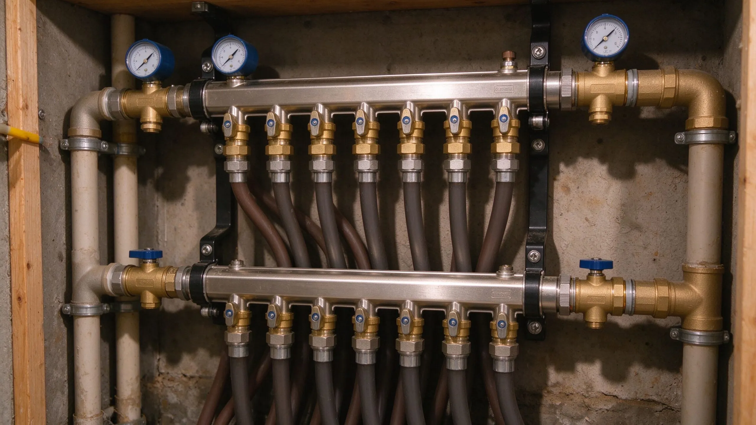
The manifold is the heart of any water-based underfloor heating system, serving as the central distribution point where heated water from the heat source is divided among multiple heating circuits. A well-designed manifold system ensures balanced flow, efficient heat distribution, and easy maintenance. This comprehensive guide covers everything you need to know about underfloor heating manifold systems.
Article by Ethan Sun, Founder & CEO, SunAura Thermal — based on 17 years of hydronic and electric heating manufacturing experience.
What Is an Underfloor Heating Manifold?
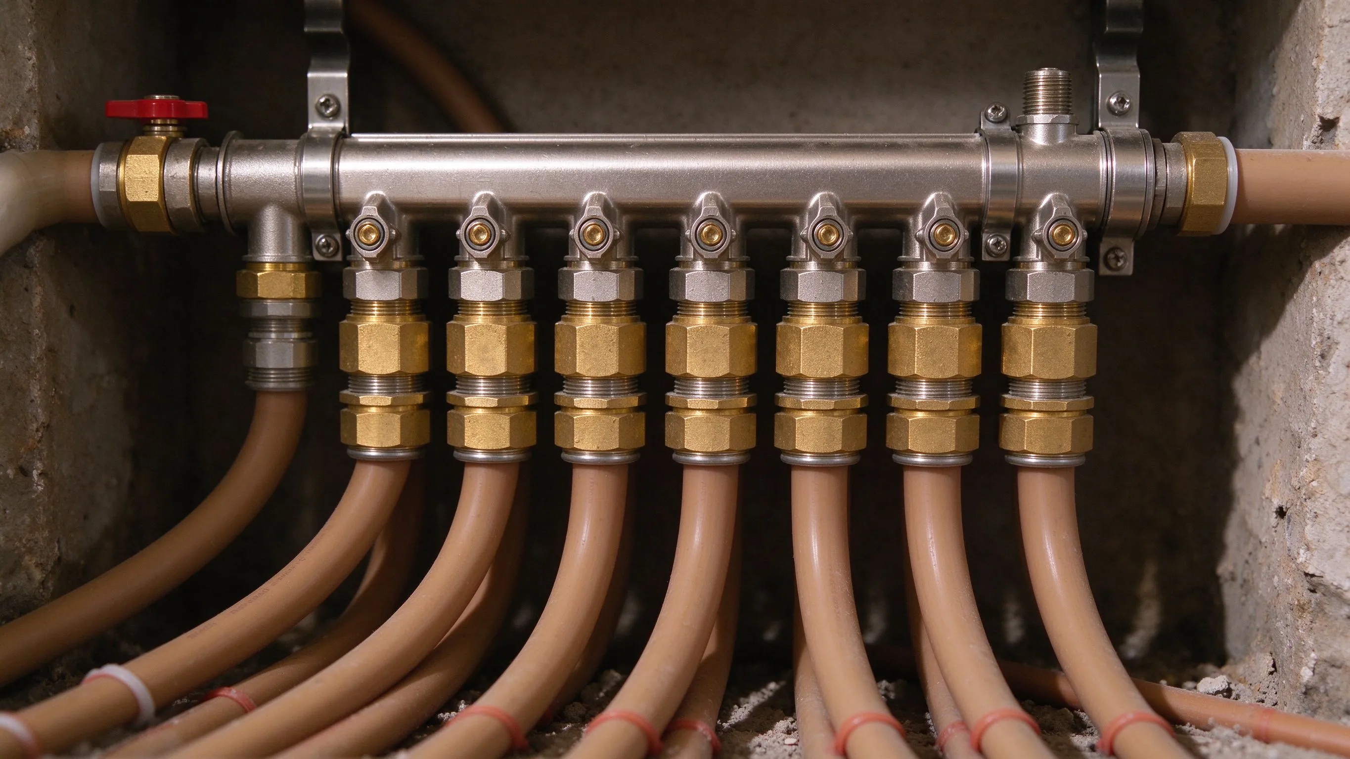
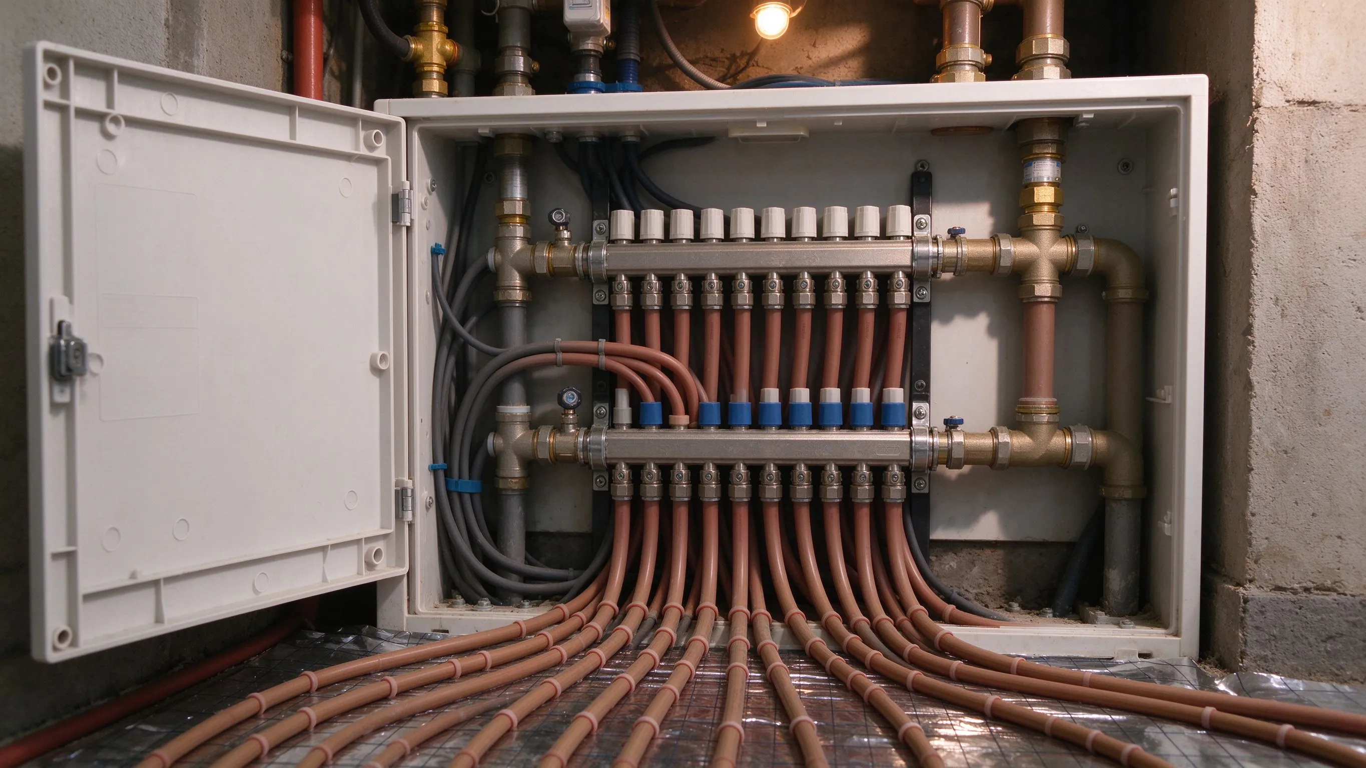
An underfloor heating manifold is a device that connects the primary heating circuit to the secondary floor heating loops. It typically consists of two parallel rails: a supply manifold that distributes heated water to the floor circuits, and a return manifold that collects cooled water. Each rail has multiple connection points, typically ranging from 2 to 12 outlets.
Core Components of a Manifold System
Supply and Return Rails
The rails are the main body of the manifold, typically made of stainless steel (grade 304 or 316) or high-quality brass. Stainless steel is preferred for its superior corrosion resistance and durability. The rails feature standardized connections, usually Eurocone (G3/4 inch) for PEX pipe connections.
Flow Meters and Adjustment Valves
Flow meters are transparent glass tubes installed on the supply manifold, providing a visual indication of the water flow rate through each circuit. The typical flow rate for underfloor heating circuits is between 2 and 5 liters per minute. The flow meter allows installers to balance the system by adjusting each circuit to the correct flow rate.
Thermometer and Pressure Gauge
Most manifold systems include thermometers on both the supply and return rails. The temperature difference between supply and return (delta-T) is an important indicator of system performance. A typical underfloor heating system operates with a supply temperature of 35-50 degrees Celsius and a return temperature 5-10 degrees lower.
Air Vent and Drain Valves
Air vents allow trapped air to be automatically or manually expelled from the system. Air in the heating circuits can cause cold spots, reduced flow, and noise. Automatic air vents continuously remove air, while manual drain valves allow the system to be drained for maintenance.
Actuators and Zone Control
Thermal actuators are motorized valves installed on the return manifold that control the flow of water through individual circuits. When connected to room thermostats, these actuators enable independent temperature control for each zone. This zone-by-zone control significantly improves energy efficiency by only heating rooms that are in use.
Design Principles and Sizing
Proper manifold sizing is critical for system performance. For PEX pipe with a 16mm diameter, the recommended maximum circuit length is 100 meters, with a typical circuit covering 80-120 square meters of floor area at 200mm pipe spacing. The manifold should be sized to accommodate the total number of circuits with at least one spare outlet for future expansion.
Hydraulic Balancing and Mixing Stations
In systems where the heat source operates at a higher temperature than required for underfloor heating, a mixing station is necessary. The mixing station consists of a thermostatic mixing valve, a circulation pump, and a bypass connection. It blends hot water from the primary circuit with cooler return water to achieve the correct supply temperature for the floor circuits.
Hydraulic balancing ensures that each circuit receives the correct flow rate regardless of pressure variations. This is achieved by adjusting the flow meters on the supply manifold. Proper balancing eliminates the common problem of some rooms being too hot while others remain cold.
Applications and Project Types
Manifold systems are used in a wide range of residential and commercial applications. In residential projects, a typical single-family home may require 2 to 4 manifolds. In commercial applications such as office buildings and hotels, larger manifold systems with 10 to 12 outlets may be used. SunAura Thermal manufactures a comprehensive range of manifold systems from basic 2-outlet units to advanced 12-outlet configurations, all carrying CE certification and backed by a 10-year warranty.
Circuit Design: Pipe Length, Spacing and Heat Output
Every underfloor heating manifold outlet feeds one continuous PEX or PEX-Al-PEX loop, and the single most important design rule is that no loop should exceed its pipe manufacturer’s recommended length. For 16 mm PEX pipe, the practical maximum is around 100 m; for 20 mm pipe it rises to 120–140 m. Loops longer than this suffer from excessive pressure drop, which starves the farthest circuits of flow and produces the classic complaint that one end of the house never warms up. The manifold exists precisely because these loop lengths must be balanced circuit by circuit, not approximated.
Pipe spacing is the second design variable. In a 100 m² living area with a design heat loss of 60 W/m², 200 mm spacing (about 5 m² of floor per 100 m loop) delivers roughly 80–100 W/m² of heat output at a 45 °C flow temperature. Around the perimeter, where heat loss is highest, installers tighten spacing to 100 mm — the so-called perimeter coil — while interior zones can use 250 mm spacing to avoid overheating the centre of large rooms. The manifold flow meters then translate that design into reality: each circuit is set to its target flow rate, typically 0.2–0.4 L/min per metre of pipe length, so that loops of different lengths all deliver their calculated share of heat.
| Parameter | Typical value | Design note |
|---|---|---|
| 16 mm PEX loop max length | 100 m | Longer loops starve on pressure drop |
| Standard spacing | 200 mm | ≈80 W/m² at 45 °C flow |
| Perimeter spacing | 100 mm | Compensates exterior-wall loss |
| Flow per circuit | 2–5 L/min | Set via manifold flow meter |
| Supply / return ΔT | 5–10 K | Below 5 K means over-pumping |
| Manifold outlets | 2–12 per bar | Specify one spare outlet |
These low-temperature design rules are what make modern water underfloor heating with heat pump low-temperature compatibility possible. Older high-temperature radiator systems run 70 °C flow; underfloor heating runs 35–50 °C, which is exactly the efficiency window where air-source and ground-source heat pumps achieve their best coefficients of performance. Specifying the manifold with the correct mixing valve and pump head is therefore the difference between a system that pairs beautifully with a heat pump and one that struggles.
Installation Best Practices: Mounting, Flushing and Pressurising
Manifold problems almost never start at the manifold itself; they start at the installation. The manifold should be wall-mounted in an accessible cabinet — typically 1.2–1.5 m above finished floor level, with 300 mm clear space below for servicing. It must be mounted level, with the supply bar above the return bar, so that the automatic air vents at the highest point can release trapped air without restriction. Before connecting loops, every circuit must be blown through with compressed air and flushed with water to remove PEX swarf, solder residue and plaster dust; a blocked loop at commissioning will silently reduce heat output for years.
Pressure testing is the next gate. The complete circuit — pipes, manifold, connections — is pressurised to 6 bar (or 1.5 times working pressure, whichever is higher) and held for at least 30 minutes before screed is poured. Any pressure drop indicates a leak that must be found while the floor is still open. During commissioning, the system is filled, vented loop by loop, and balanced using the flow meters. This balancing procedure — measuring supply and return temperatures on each circuit and adjusting until all loops converge on the design ΔT — is described in detail in our guide to underfloor heating commissioning, testing and balancing, and it is the single biggest determinant of comfort in a multi-room installation.
Actuators are then fitted to the return bar and wired to room thermostats through a central wiring centre. For zoned systems, every manifold outlet that serves a separate room gets its own 230 V thermal actuator, and the wiring centre provides a shared live feed plus a floor-sensor connection for any thermostat that needs one. Skipping the wiring centre and chaining actuators directly is a common shortcut that produces fault-finding nightmares a year later.
Controls, Actuators and Weather Compensation
A manifold is only as intelligent as the devices bolted onto it. Thermal actuators on the return bar open and close each loop in response to room thermostats; when a room reaches setpoint, the actuator closes, flow stops in that loop, and water circulates through the remaining open circuits. Weather-compensated controls add a further layer: they measure outside temperature and adjust the manifold’s supply water curve so that colder days receive warmer water and mild days receive less. In a typical European winter this single feature cuts heat output by 10–15% during the shoulder months without any perceptible change in room comfort.
For properties that already use electric heating in some rooms and hydronic in others, SunAura supplies both product families from the same factory — see our thermostats and controls range for the room thermostats, actuators and wiring centres that complete a manifold installation. Mixing brands across a manifold system is technically possible, but firmware protocols, sensor ranges and terminal layouts differ, which is why most installers standardise on one control family per project.
For installers and specifiers comparing manifold brands, the decisive questions are simple: what is the pressure-test standard, are flow meters and actuators included or optional, and can spare outlets be added on site. SunAura answers all three on the datasheet, rather than in a quotation cycle.
Factory Evidence: Manufacturing, Testing and Standards
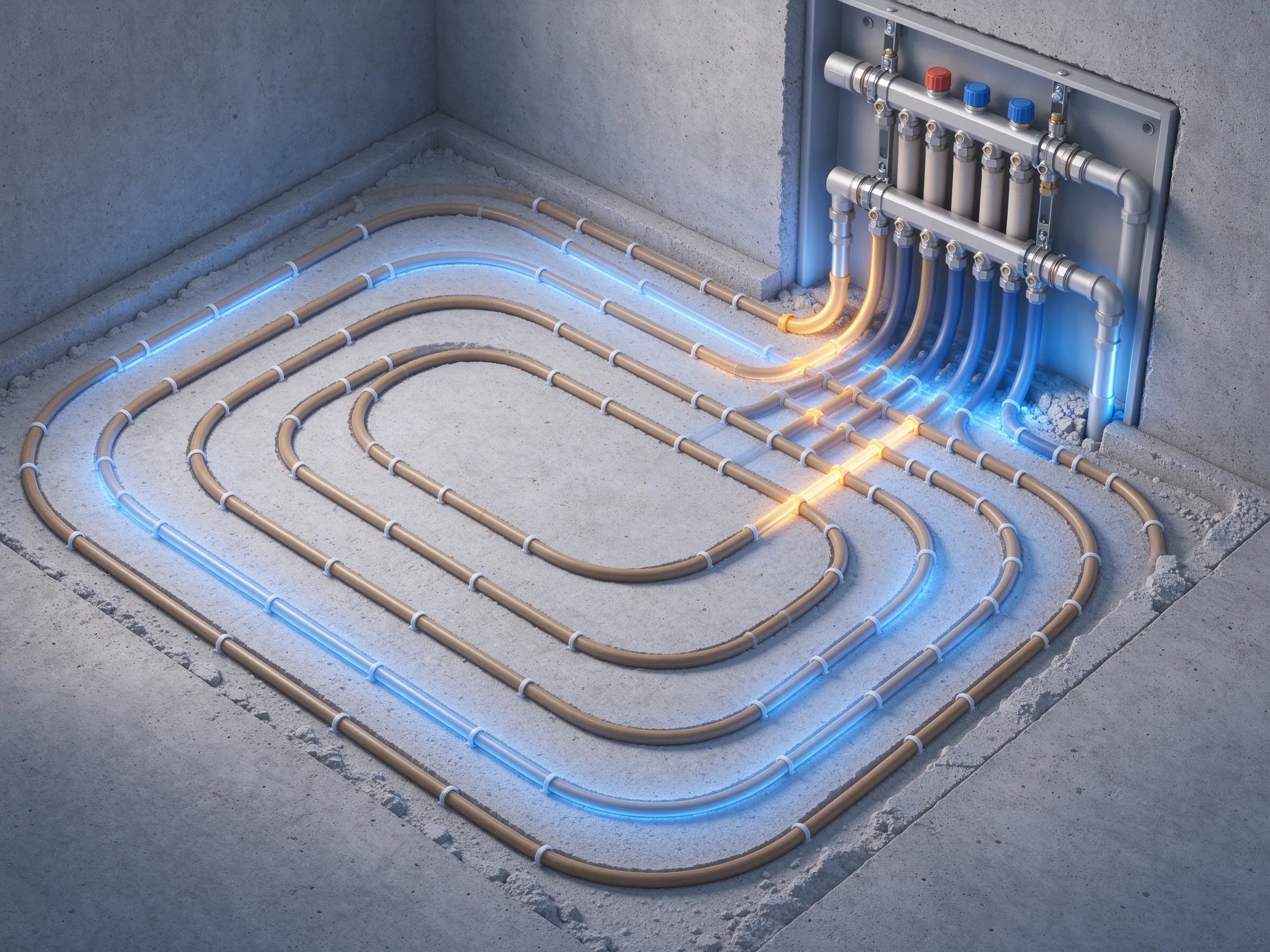
SunAura Thermal has manufactured water underfloor heating systems and manifold assemblies at our Qingdao Huangdao facility since 2008, now in our 17th production year. Our stainless-steel manifolds are built to CE standards under ISO 9001, ISO 14001 and ISO 45001 management systems, and each assembly undergoes pressure testing at 10 bar before despatch, per SunAura factory records. The range covers 2-through-12 outlet configurations, with optional integrated mixing stations, circulation pumps, weather-compensated controls and thermal actuators — all sourced from the same factory that supplies OEM underfloor heating manufacturer programmes to distributors across more than 50 countries.
Regulatory context reinforces why manifold design matters. The EU Energy Performance of Buildings Directive requires member states to ensure new and renovated buildings meet minimum energy performance levels, which in practice means zoned, low-temperature hydronic systems rather than oversized single-loop radiators. Organisations such as ASHRAE publish the design standards (including 90.1 for commercial buildings) that govern how these systems are sized, and a well-balanced manifold is the hardware component that turns those design equations into actual room temperatures.
Frequently Asked Questions
How many manifold outlets does a typical house need?As a rule of thumb, one outlet per heated room or zone, plus one spare. A three-bedroom detached house with kitchen, living room and two bathrooms typically needs 6–8 outlets; an open-plan house with two large zones may need only 3–4. Always size up by one outlet — future renovations rarely reduce heating demand.
Can I add more loops to an existing manifold later?Only if the manifold was specified with a spare outlet and the pump and mixing station have the hydraulic capacity. Most manifolds are modular, so additional bars can be bolted on, but the pump head and boiler or heat-pump output must be rechecked before expanding. Retrofit additions are easier with manifolds ordered with 1–2 spare outlets at the time of installation.
Why is one room colder than the others?Ninety percent of the time it is a balancing problem: that circuit’s flow meter is set too low, the loop is too long, or air is trapped in the loop. Bleed the circuit, then re-measure flow and ΔT. If the room is still cold after balancing, the loop may be shorter than design or the pipe spacing too wide.
Stainless steel or brass manifold — which is better?Stainless steel (grade 304 or 316) offers superior corrosion resistance, longer service life and better tolerance of modern low-oxygen systems. Brass is cheaper but more vulnerable to dezincification over decades. For a system expected to last 30+ years, stainless steel is the standard choice in new installations.
Do manifolds need maintenance?Once a year, during heating season start-up, check the automatic air vents, record supply and return temperatures, and confirm each flow meter reads within design. Every five years, inspect the filter on the return bar and flush it. Beyond that, a well-installed manifold is essentially maintenance-free for decades.
Conclusion
The manifold system is a critical component of any water-based underfloor heating installation. By understanding the components, design principles, and applications, installers and homeowners can make informed decisions that ensure optimal heating performance for decades to come.
Related Products & OEM Inquiries
Looking for underfloor heating manifold and design components or a factory-direct OEM/ODM partner? Explore our complete electric underfloor heating systems, then request a quote for your project — we supply distributors, installers and brands in 50+ countries.